First Project
User guide
2025-07-04
Plzeň (Pilsen), Czech Republic
Contents
2 Creating a new project
3 Compiling and running a project
4 Adding a user interface (HMI)
5 Ready for interaction with the outer world
Chapter 1
Introduction
The process of creating a control algorithm will be demonstrated on a very simple example with four Boolean variables representing manual switches. In In the follow-up manual [1], two of them will be replaced by physical inputs of the platform. A software timer will be used for measuring the time when the variables are true (i.e. the switches are in the on position). A Boolean signal will indicate that the interval of predefined length has elapsed.
Chapter 2
Creating a new project
The project configuration is created using the REXYGEN Studio program. Each project consists of at least two .mdl files. The first file is the main file of the project, which is used for configuration of tasks, drivers, priorities and timing. The other file(s) contain the individual control algorithms (tasks).
First, we will create the example 0101-01 from the example library from scratch (All examples that are part of the REXYGEN Studio installation are marked with their unique code. The most up-to-date examples are available with the latest installation of the development tools or at https://www.rexygen.com/example-projects/). Standard approach:
- Run the REXYGEN Studio program. Start with a plain project and select a folder to save the project files in (e.g. D:\GettingStarted).
- The folder will contain two important files:
- myproject_exec.mdl
- myproject_task.mdl
- The myproject_exec.mdl is the project main file. It contains one EXEC block from the
EXEC library. The other block is the TASK block from the same library and it is renamed
to myproject_task to reference the second file of the project (myproject_task.mdl),
which will contain the algorithm (the so-called task).
- The task is connected to the Level0 output of the EXEC block and therefore its timing is defined by tick and ntick0 parameters of the EXEC block.
- The EXEC block (and any other block) can be configured by double-clicking on it. A block
parameters and properties dialog appears. The parameters of all blocks of the REXYGEN
system are described in the Help (press the F1 key) and in the Block reference
manual [2].
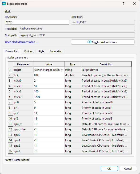
- Note that tick=0.05 and ntick0=2, therefore the task will run each 100 milliseconds (). There is no need to change any parameter at the moment. Close the dialog.
- You can delete all the descriptive texts in project files. These have no effect on the functionality and can be considered programmer’s comments.
- Open the Block Library - Choose Window->Block Library from the menu or use the Ctrl+L shortcut. The library will appear in the right part of the studio, if it wasn’t there already.
- By default, the library is in Tree view mode where the blocks are organized in
sublibraries. Their location is always denoted as sublibrary/block, e.g. LOGIC/AND for
the logical AND block in the LOGIC sublibrary. Inside a sublibrary, the blocks are ordered
in alphabetical order.
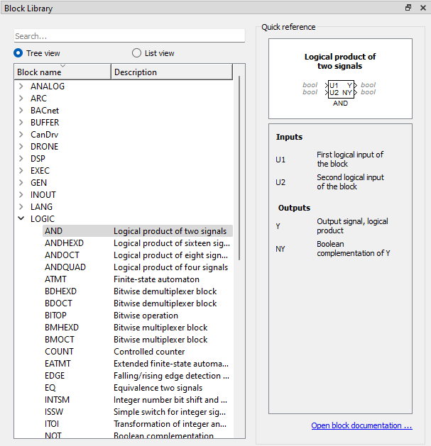
- You can also switch the library to List view mode, where all the blocks are sorted alphabetically, regardless of the sublibrary they belong to.
- Locate the following function blocks in the Block Library and drag them to the task
file:
- MATH/CNB – constant of type Boolean. Once dropped, double-click to display the parameters dialog and change the name to CNB_SWITCH1. Also set the parameter .
- LOGIC/OR – logical OR. Rename it to OR_A.
- LOGIC/AND – logical AND.
- LOGIC/TIMER – a timer block. Set parameter , .
- INOUT/Display – a display to show values in real-time.
- ARC/TRND – real-time recording. Set parameters , , leave the default values otherwise.
- MATH/CNB – constant of type Boolean, change name to CNB_RUN, set parameter .
Tip: You can also insert blocks by starting to write their name and selecting the desired block from the whisperer.
- Duplicate the CNB_SWITCH1 block with right mouse button dragging. Or simply Copy&Paste the block.
- Duplicate the block 2 more times.
- Duplicate also the OR_A block. Rename the duplicate to OR_B.
- Connect the blocks as shown below. To connect the blocks, drag the output arrow of one
block to the input arrow of the other block using the left mouse button. The connection
will be established when the line goes bold and green. After releasing the mouse button
you can recognize a successfully connected line by its style. A full line terminated by a
full arrow at the input of the connected block indicates a valid connection. A dashed red
line ending with a thin arrow indicates an unconnected line. New branch of an
existing line can be created by dragging an existing line with the right mouse
button.
At this moment the executive configuration myproject_exec.mdl and the corresponding myproject_task.mdl file with the algorithm are ready. The algorithm will be evaluated in the direction of the arrows, starting from the source CNB blocks, passing through the OR, AND and TIMER blocks and finishing at the Display and TRND blocks. Congratulations, your first project is ready for compilation!
Chapter 3
Compiling and running a project
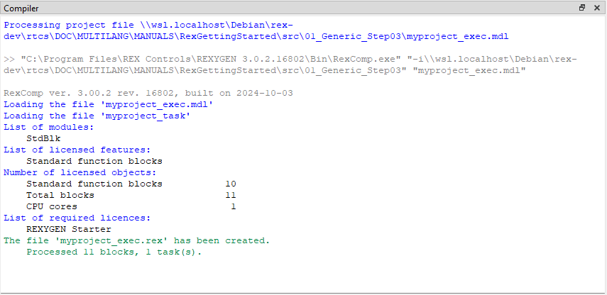
The developed algorithm must be compiled to binary form prior to deploying. Pick Project/Compile from the menu or use the icon from the toolbar. The compiler output is displayed in the Compiler window. If no error is found, the myproject_exec.rex file is created.
At this moment it is possible to deploy the control algorithm to the target platform. Use Project/Compile and Download in the menu or click the icon for this purpose. A dialog for defining the target device appears upon successful compilation.
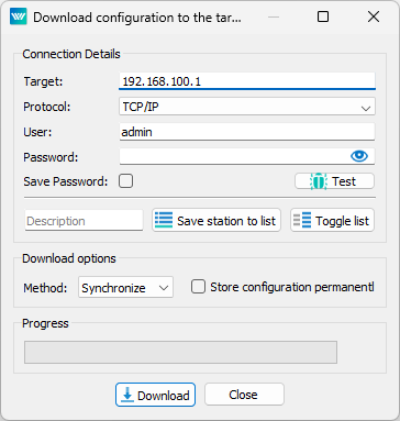
Enter your platform’s IP address in the Target field and login information. The default user is admin and the default password is blank. Leave the other elements unchanged and click Download.
If there is no licence on your platform, you need to get one first. You can get a DEMO licence for free. See [3] for details and come back afterwards.
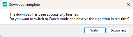
As soon as the download is complete it is possible to switch the REXYGEN Studio to the so-called Watch mode and watch the control algorithm in real-time – click Watch.
In the Watch mode, the background of all files goes gray and you cannot move or delete any blocks or connections. Right-click the TIMER block and select Watch selection in the menu to watch the inputs and outputs of the timer. You can do the same with the OR and AND blocks (or any other selection).
Now it is possible to double-click the CNB_SWITCH1 block and change the Boolean variable to (tick the checkbox and click OK). Once you do the same with the CNB_SWITCH3 block, the outputs of both OR blocks are on and the Y output of the AND block goes on and the TIMER starts to count down. Observe the rt output. (Do not get confused by the default 1 second refresh rate of the Watch mode. The algorithm on the target device runs each 100 milliseconds as mentioned earlier.) Once the timer reaches zero, its output Q is set to on and it remains on as long as the U input is on.
You can double-click the TRND block to see the signals in a real-time graph. The red line is the output of the OR_A block, the magenta line is the output of the OR_B block, the green line is the remaining time of the timer and the blue line is the Boolean output of the timer.
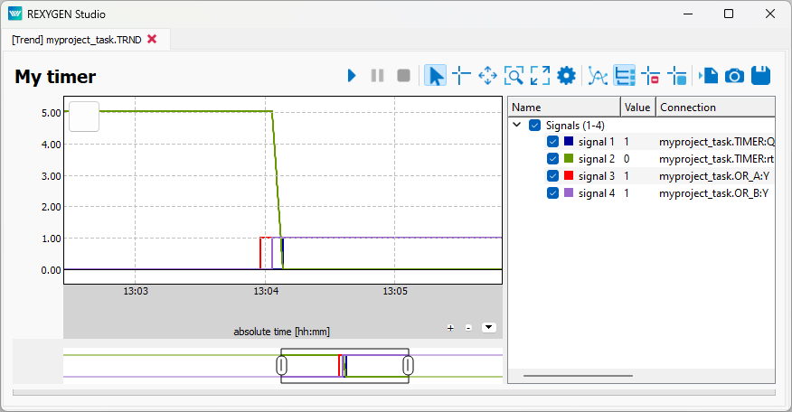
Try turning the CNB blocks off and change the pt parameter of the TIMER block. Afterwards turn the CNB blocks on again and observe the signals in the TRND block again. As you can see, you can modify any parameter in real-time, which allows you to fine tune your algorithm.
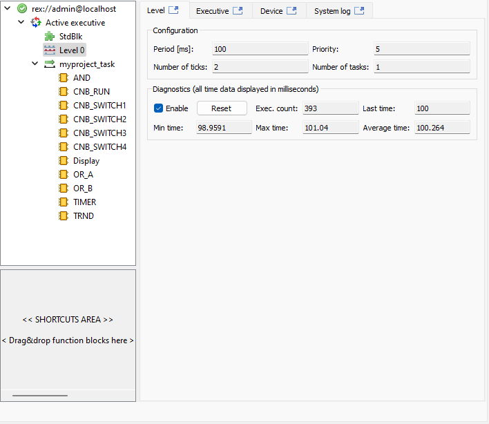
It is also possible to open a Diagnostics tab of the algorithm. Pick Target/Diagnostics from the menu or click the icon and you will see the algorithm in a tree view which allows you to monitor the control algorithm in full detail. You can verify that the sampling rate of your algorithm is indeed 100 milliseconds. You can also adjust parameters of individual function blocks, which has the same effect as modifying them directly in the Block properties dialog.
Now you can switch REXYGEN Studio back to the Development mode. You can do so by deactivating the Watch mode (use the icon). You are offered synchronization of the changed parameters with the source files of the project, choose No at this moment.
All changes made while in the Watch mode are not permanently stored in the target device (unless you decide so, see [4]). Upon restarting the RexCore runtime module the algorithm will start with the parameters defined in the project source files, which were valid when compiling and downloading the algorithm to the target device. To apply the changes permanently, you have to transfer the changes to the source files and Compile and Download the project one more time which defines new startup values.
Chapter 4
Adding a user interface (HMI)
The next step in developing a control algorithm is its user interface, or HMI, Human-Machine Interface. It allows anyone (even those who are not familiar with the REXYGEN system) to interact with the algorithm. The HMI of the REXYGEN system relies on modern web-based technology and the HMI is therefore accessible via web browser on desktop PC, tablet or smartphone.
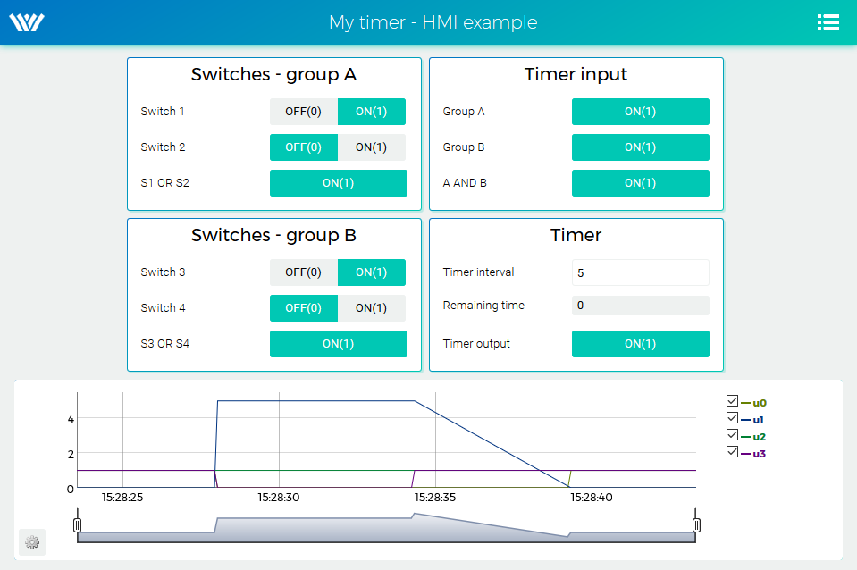
In this tutorial, a simple HMI will be created using the so-called WebBuDi technology. It provides very simple indicators and input elements to interact with the control algorithm via a web page (Web Buttons and Displays).
The steps to create the HMI are described below. This is how the HMI will look like in the end:
- In the folder with the project files, create a hmisrc subfolder. Inside this folder, create a
file named index.hmi.js and edit it with your favorite text editor. The content should
be the following:
REX.HMI.init = function(){

//Indicators and virtual switches - group A
  var switchesA = {
    column: 1,
    title: 'Switches - group A',
    rows: [
      {type: 'DW', alias: 'switch1', desc: 'Switch 1', cstring: 'myproject_task.CNB_SWITCH1:YCN'},
      {type: 'DW', alias: 'switch2', desc: 'Switch 2', cstring: 'myproject_task.CNB_SWITCH2:YCN'},
      {type: 'DR', alias: 'S1orS2', desc: 'S1 OR S2', cstring: 'myproject_task.OR_A:Y'},
    ]
  };
  REX.WebBuDi.addSection(switchesA);

//Indicators and virtual switches - group A
  var switchesB = {
    column: 1,
    title: 'Switches - group B',
    rows: [
      {type: 'DW', alias: 'switch3', desc: 'Switch 3', cstring: 'myproject_task.CNB_SWITCH3:YCN'},
      {type: 'DW', alias: 'switch4', desc: 'Switch 4', cstring: 'myproject_task.CNB_SWITCH4:YCN'},
      {type: 'DR', alias: 'S3orS4', desc: 'S3 OR S4', cstring: 'myproject_task.OR_B:Y'},
    ]
  };
  REX.WebBuDi.addSection(switchesB);

//Timer input
  var timerInput = {
    column: 2,
    title: 'Timer input',
    rows: [
      {type: 'DR', alias: 'inputA', desc: 'Group A', cstring: 'myproject_task.AND:U1'},
      {type: 'DR', alias: 'inputB', desc: 'Group B', cstring: 'myproject_task.AND:U2'},
      {type: 'DR', alias: 'AandB', desc: 'A AND B', cstring: 'myproject_task.AND_:Y'},
    ]
  };
  REX.WebBuDi.addSection(timerInput);

//Timer settings and status
  var timer = {
    column: 2,
    title: 'Timer',
    rows: [
      {type: 'AW', alias: 'interval', desc: 'Timer interval', cstring: 'myproject_task.TIMER:pt'},
      {type: 'AR', alias: 'rt', desc: 'Remaining time', cstring: 'myproject_task.TIMER:rt'},
      {type: 'DR', alias: 'timerQ', desc: 'Timer output', cstring: 'myproject_task.TIMER:Q'},
    ]
  };
  REX.WebBuDi.addSection(timer);

  //Add real-time trend
  REX.HMI.Graph.addTrend({cstring: 'myproject_task.TRND'});
  REX.HMI.Graph.setMaxBufferSize(200);

  // Change title of the page
  REX.HMI.setTitle('My timer - HMI example');
}
- This file will be processed when compiling the project. However, it is necessary to add
the EXEC/HMI block into the project main file first.
- Double-click the HMI block to edit its parameters. Set and confirm. WebWatch is another type of HMI, which you do not need at the moment. See [5] for details, it is a very interesting tool for developers and technicians.
- The HMI is now an integral part of your project. Compile the project again and you will see that the compile log contains more information. The index.html file is generated from the source index.hmi.js file. All the HMI files are generated into the hmi subfolder (HTML, JS and CSS files) and included in the resulting binary myproject_exec.rex file.
- After you download the project to the target device, you can access the HMI via web
browser. Go to menu Target/Web Interface which will open the webpage. Remember the
default login credentials: admin with blank password.
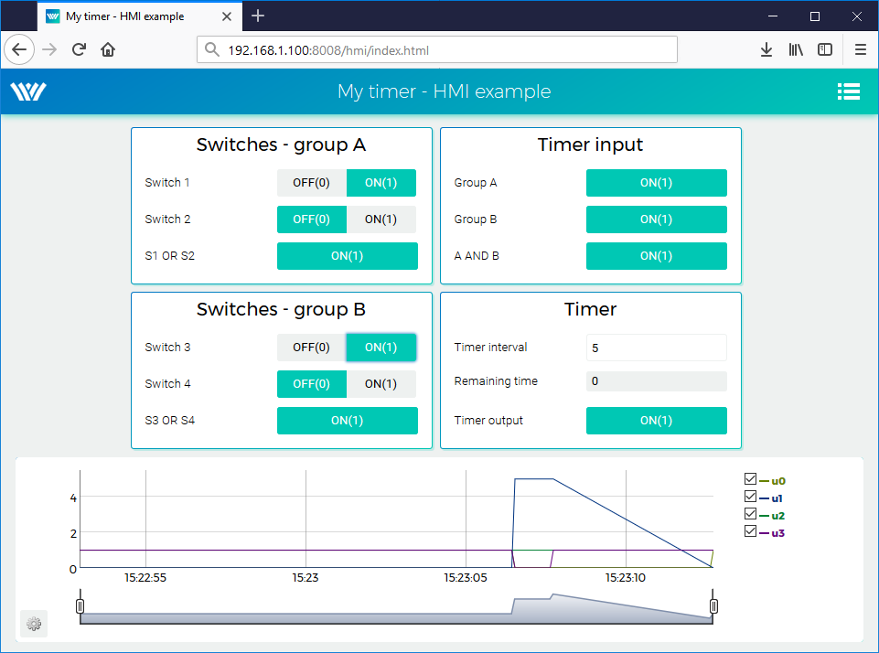
- You can toggle the switches and observe the results. The virtual switches are linked to the individual CNB function blocks therefore the effect is the same as toggling the values directly in REXYGEN Studio.
- You can also change the timer setting and shorten or lengthen the interval.
- See [5] for detailed information about WebBuDi elements and possible customization (colors, backgrounds etc.).
- The default URL address is http://192.168.1.100:8008/hmi/index.html (replace 192.168.1.100 with the IP address of your platform).
- The default port of the webserver (8008) can be changed in RexCore settings. See [6] for details.
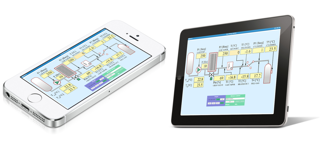
Please note that there is also a program called REXYGEN HMI Designer, which allows you to create graphical user interfaces. The accompanying manual [7] shows the steps to create a basic graphical interface for the example created above. The more complex HMIs in the images below are shown for inspiration purposes only.
Chapter 5
Ready for interaction with the outer world
Well done! You have created the example 0101-01 from scratch (All examples that are part of the REXYGEN Studio installation are marked with their unique code. The most up-to-date examples are available with the latest installation of the development tools or at https://www.rexygen.com/example-projects/). You have learned the basic workflow for developing and running your algorithms using the REXYGEN system, which is the same for all platforms. Now, it’s time to add the so-called input-output drivers so that the algorithm can interact with sensors, actuators, and external data. The configuration of inputs and outputs specific to target devices, based on the example project presented in this chapter, is discussed in the I/O Configuration of Target Platforms guide [8].
Bibliography
[1] REX Controls s.r.o.. Konfigurace vstupů a výstupů na cílových platformách, 2024. .
[2] REX Controls s.r.o.. Function blocks of REXYGEN – reference manual, 2024. .
[3] REX Controls s.r.o.. REXYGEN Licensing – User guide, 2024. .
[4] REX Controls s.r.o.. REXYGEN Studio – User manual, 2024. .
[5] REX Controls s.r.o.. REXYGEN HMI – User manual, 2024. .
[6] REX Controls s.r.o.. RexCore – User manual, 2024. .
[7] REX Controls s.r.o.. Tvorba HMI v REXYGEN HMI Designer, 2024. .
[8] REX Controls s.r.o.. I/O Configuration of Target Platforms, 2024. .
Documentation reference number: 17331
2025 © REX Controls s.r.o., www.rexygen.com