HMI creation in REXYGEN HMI Designer
User guide
2025-07-04
Plzeň (Pilsen), Czech Republic
Contents
2 Adding the first HMI components
3 Linking HMI components with the running algorithm
4 Adding more HMI components
5 Additional links to the running algorithm
6 The final steps
In the manual [1], the creation of a simple WebBuDi user interface is described in detail. The REXYGEN development tools also include the REXYGEN HMI Designer program, which is a tool for designing custom graphical visualisations using predefined components (Defining custom components is also possible, but it requires some programming in Javascript.). REXYGEN HMI Designer is based on the well-known open-source vector editor InkscapeTM https://inkscape.org/en/.
In this accompanying manual, we will develop an alternative HMI for example 0101-01, the creation of which was described in [1]. Similar to the WebBuDi user interface, the SVG file created using REXYGEN HMI Designer will serve as a source file, which will become part of your REXYGEN project. During project compilation, the SVG file will be processed and converted into HTML, JS, and CSS files.
Chapter 1
Initializing the HMI design
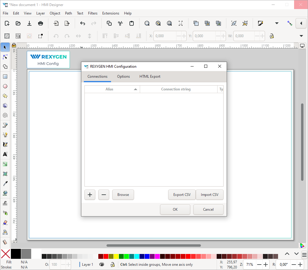
After launching REXYGEN HMI Designer, you will find a blank page with an initialised visualisation. The HMI is configured through the REXYGEN HMI extension. In the menu, navigate to Extensions REXYGEN HMI Edit HMI Config.
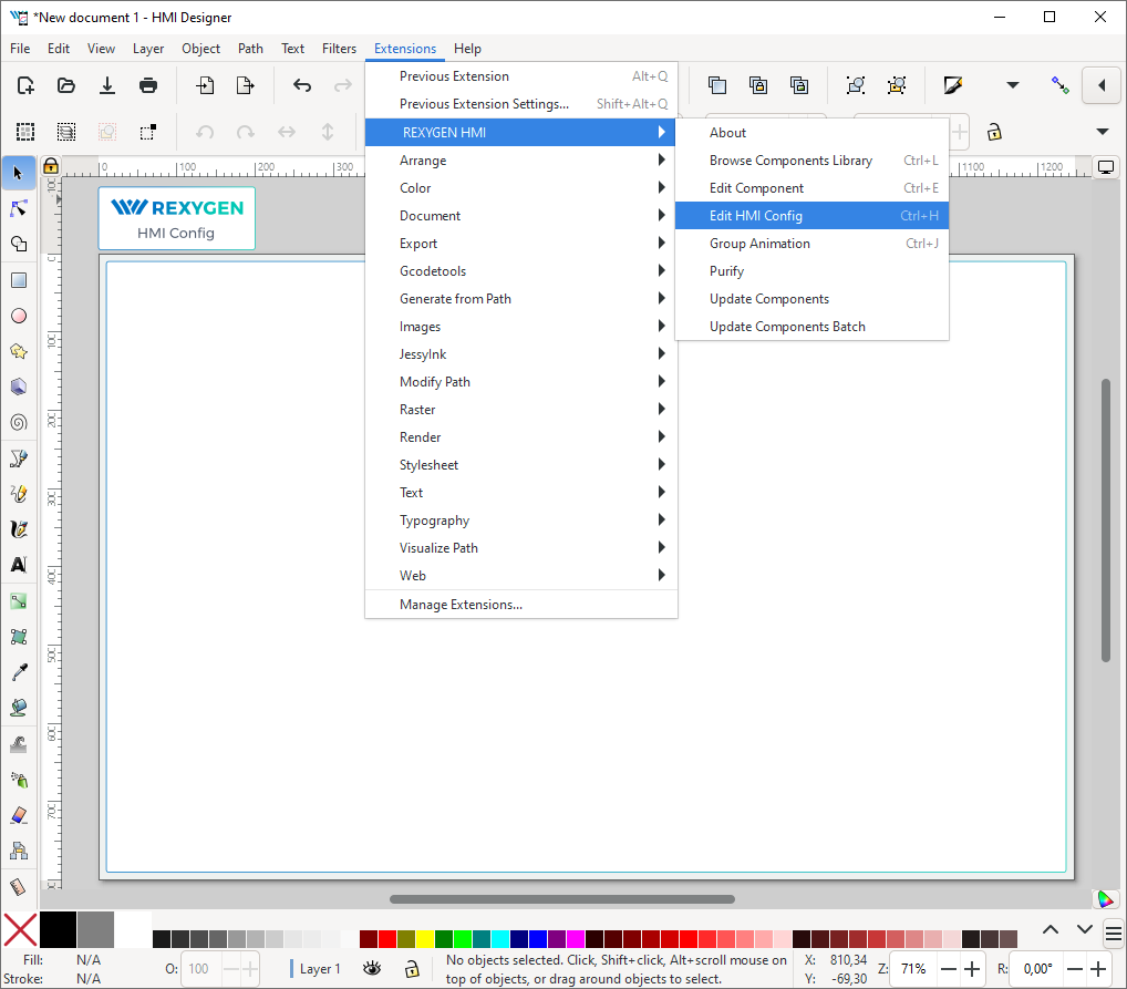
This extension is represented by a special component in the top left corner above the drawing. The component contains general HMI settings. For now, close the configuration dialog by clicking the OK button.
In order to include the HMI during the REXYGEN project compilation, the file name has to end with .hmi.svg. Save the file as e.g. designer.hmi.svg to the hmisrc subfolder of your project. Use the standard File Save as menu.
Note: If you want to replace the WebBuDi interface with the REXYGEN HMI Designer interface just delete the index.hmi.js and save the HMI as index.hmi.svg.
Chapter 2
Adding the first HMI components
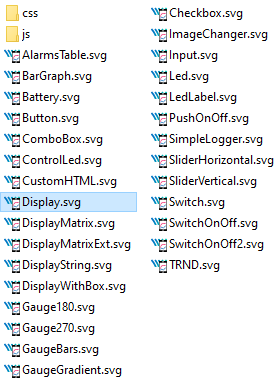
Now we will add some displays and inputs. The REXYGEN HMI Designer contains a library of components which you can use to build your HMI. The library is available through Browse Components Library extensions. Navigate to Extensions REXYGEN HMI Browse Components Library (Ctrl+L). It will open the explorer window with several folders. Open the GENERAL folder and drag&drop the Display to the drawing. The display will be used as an indicator of the remaining time in the TIMER function block.
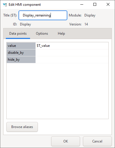
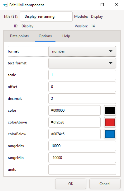
For configuration of the display settings select the display by mouse click on top of it and use the Edit Component extension from Extensions REXYGEN HMI Edit Component (Ctrl+E). When the configuration dialog is opened you can change the Title to Display_remaining. The Edit Component dialog has two tabs: Data points and Options.
The Data points tab contains three items defining the behavior and animations of the component. Each data point contains an alias, which is in fact a connection to live data from the REXYGEN algorithm.
- value – The value to display.
- disable_by – If true the display is disabled and data are no longer updated.
- hide_by – If true the display is hidden.
The value property contains $T_value. The $T will be later automatically substituted by the Title of the component, resulting in the Display_remaining_value alias. The disable_by and hide_by data points are optional. Leave them blank at the moment.
The Options tab contains several properties which are specific for the Display component.
You can find the description of each component and property in [2]. Leave the default values
for now and press OK.
Note: Each component is in fact one SVG group with unique content. You can
copy the components all over the screen using copy (Ctrl+C) and paste (Ctrl+V)
approach.
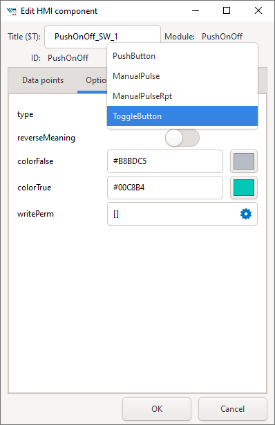
Now we will add controls for all the switches (CNB blocks). All of them will be controlled using the PushOnOff components. Add them from the library. Select the first PushOnOff and open the editor dialog Extensions REXYGEN HMI Edit Component (Ctrl+E). Change the title to PushOnOff_SW_1 and select the Options tab. Select the ToggleButton item in the type property list. Close the Edit Component dialog using OK button. Copy-paste the button three times and remember to change the titles to PushOnOff_SW_2, PushOnOff_SW_3, PushOnOff_SW_4.
Now we have four PushOnOff buttons and one Display and we want to link all components with live data from the target device.
Chapter 3
Linking HMI components with the running algorithm
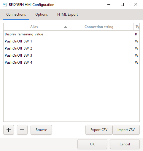
Open the HMI Configuration dialog either using Extensions REXYGEN HMI Edit HMI Config or just unselect all components in the drawing (click outside any component) and press Ctrl+E. The configurator parses all components and creates a list of used Aliases. Each of them should be linked with one signal in the running algorithm. You can either fill in each connection string manually or you can use the Browse function.
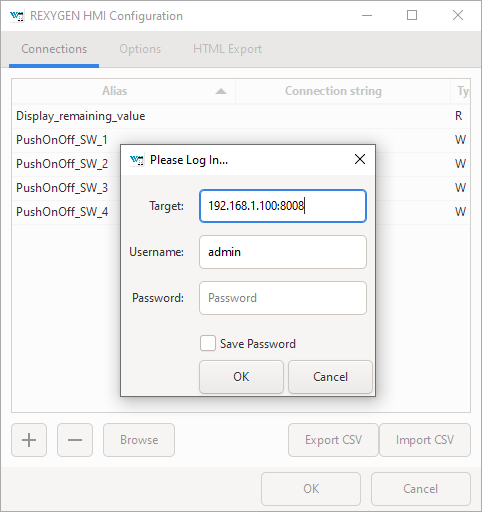
The Browser requires a target device with running algorithm. Make sure the algorithm is running, see manual [1]. Also the target URL must be set. Press Browse button. The login dialog will be opened. Change Target to 192.168.1.100:8008 (replace 192.168.1.100 with the IP address of your platform). Unless you changed the login credentials, use the default username admin with an empty password. After a successful login the connection tab is expanded with a tree-view of the running algorithm (you have already seen this tree-view in algorithm diagnostics).
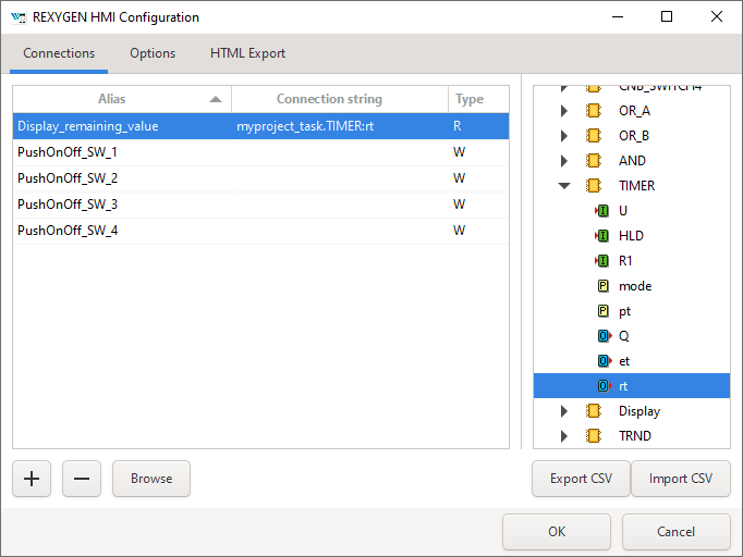
Select Connection String field of the Display_remaining_value item and afterwards browse the tree to the TIMER block and double-click the rt parameter. The connection string of the parameter is copied to the Display_remaining_value alias, which is shown in the next figure.
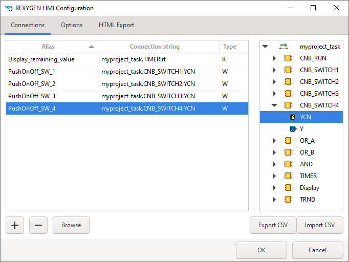
Once the display is linked we will also link the switches. Just browse the tree to CNB_SWITCH1, select the Connection String field of the PushOnOff_SW_1 alias and double-click the YCN parameter. Repeat this for the remaining connection strings. Afterwards press OK to save the settings and close the dialog.
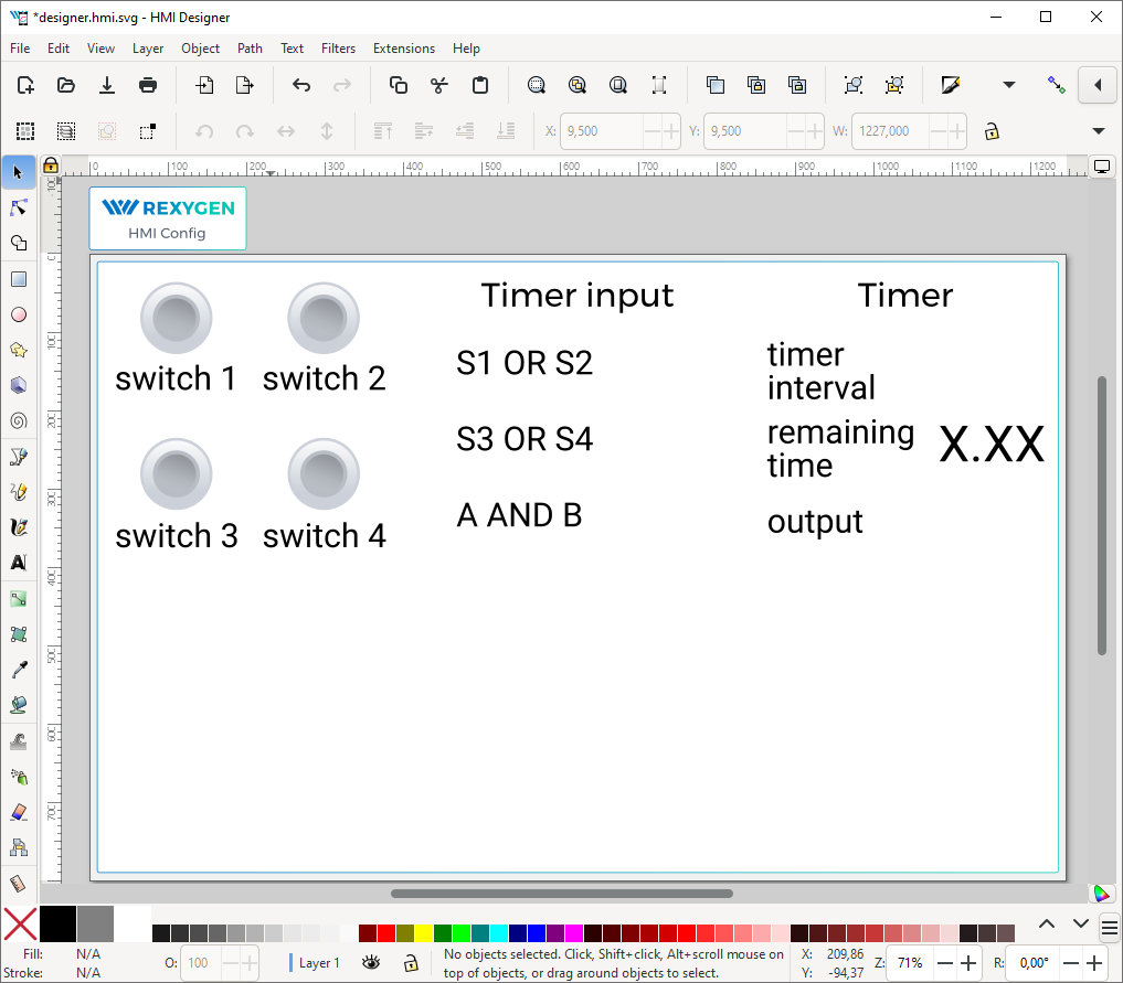
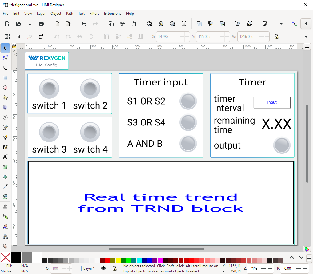
The interactive components in REXYGEN HMI Designer are just parts of the drawing. The user can position the components arbitrarily and add as many decorative static components to as needed. We will add some text descriptions to distinguish individual buttons. Use the Text Tool (F8), click anywhere in an empty space and start typing. Pick the Selector Tool (F1) afterwards and move the texts and buttons.
Note: More information about custom drawing can be found in Inkscape tutorials (See the Help Tutorials Inkscape: Basic)
Chapter 4
Adding more HMI components
Next we will add more components to control the timer and show the status of the OR and AND blocks. Open the Elements library (Ctrl+L) and add one Input and four Led components. The LEDs will show the status of Boolean values and the Input will be used for changing the default timer interval value.
In the Led components just edit the Title via the Edit Component extension (select the component by single click and press Ctrl+E). The titles should be Led_OR_A, Led_OR_B, Led_AND, and Led_TIMER_OUT respectively. Finally edit the Input component by changing the Title to Input_interval.
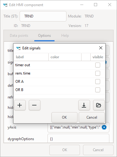
The last component we need is a graph showing the time-plot of data from the TRND block. Use the components library (Ctrl+L) and add a TRND component. You can adjust its size to fit the desired position. Edit the component (Ctrl+E) and change the Title to TRND and switch to the Options tab. Double-click the signals property. Add the following labels using the plus (+) button: timer out, rem. time, OR A, OR B. These labels will be shown in the legend of the graph.
Chapter 5
Additional links to the running algorithm
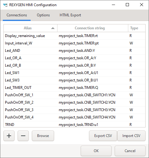
When all the components are in place we link them to the running algorithm again. Just repeat the procedure described in Section 3, open the HMI Configuration dialog (Extensions REXYGEN HMI Edit HMI Config) and browse the running algorithm to pair the remaining aliases with corresponding connection strings. The list is shown in the following image.
Chapter 6
The final steps
Congratulations, your first graphical HMI is almost ready! Add a few rectangles which will visually divide the HMI into individual sections. Use the Rectangle Tool (F4), draw the rectangle, pick a color from the palette and send the rectangle to the background using the End key. Do not forget to save the drawing.
As mentioned earlier, the *.hmi.svg files in the hmisrc folder are automatically processed while the project is compiled in the REXYGEN Studio application. The project main file must contain the HMI block with GenerateRexHMI parameter set to on. This was already set when creating the first project in the manual [1], so you should have everything ready.
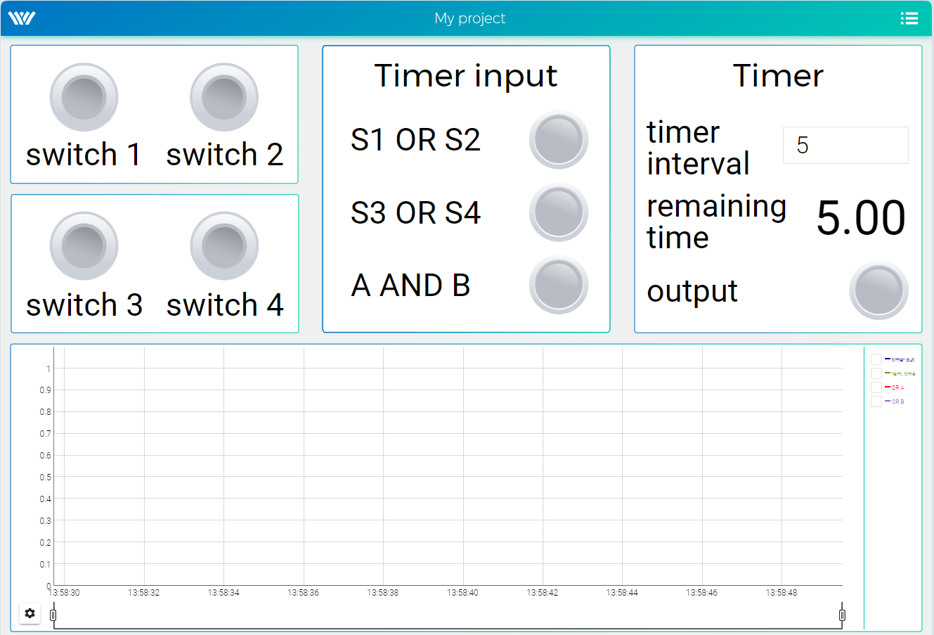
Once you compile the project again and download it to your platform, the HMI will be
accessible via a web browser. Navigate to
http://192.168.1.100:8008/hmi/designer.html (replace 192.168.1.100 with the IP address
of your platform). You will see your HMI with live data.
This tutorial covers only the very basic components. If you want to get more information about additional components, see [2].
Bibliography
Documentation reference number: 17331
2025 © REX Controls s.r.o., www.rexygen.com