Driver for communication with Siemens PLCs
(S7Drv module of the REXYGEN system)
User guide
Plzeň (Pilsen), Czech Republic
2025-07-04
Contents
1.1 Introduction
1.2 System requirements
1.3 Installation of the driver on the host computer
1.4 Installation of the driver on the target device
1.4.1 Windows machines
1.4.2 Linux machines
2 Including the driver in the project
2.1 Adding the S7Drv driver
3 Driver configuration
3.1 Connecting the inputs and outputs in the control algorithm
4 Implementation details
5 Troubleshooting
Chapter 1
The S7Drv driver and the REXYGEN system
1.1 Introduction
This manual describes the S7Drv driver for data exchange between the REXYGEN system and Siemens PLCs and operator panels. (Siemens and STEP are registered trademarks of Siemens AG.) The driver uses the same communication protocol as the STEP7 development environment. Only Ethernet communication is supported.
The S7Drv driver relies on the Snap7 communication suite [1].
The REXYGEN system can act as Client (emulation of PG – STEP7) or Server (emulation of Siemens PLC).
1.2 System requirements
The S7Drv driver can be used on all target platforms supported by REXYGEN.
1.3 Installation of the driver on the host computer
The S7Drv driver is included in the installation package of the Development tools of the REXYGEN system. It is necessary to select the corresponding package in the installer.
1.4 Installation of the driver on the target device
1.4.1 Windows machines
The target part of the driver, which is used for communication with Siemens devices on Windows 10/11 is included in the Development tools of the REXYGEN system as mentioned above.
1.4.2 Linux machines
If there is no RexCore runtime module installed on your target device, install it first using the Getting started guide of the REXYGEN system [2]. The installation encompasses all essential drivers, including S7Drv.
If you wish to install S7Drv separately, you can do so from the command line using the
following command:
Debian:
sudo apt-get install rex-s7drvt
WAGO:
The S7Drv driver is included in the REXYGEN system image for the WAGO platform and no
action is required.
Chapter 2
Including the driver in the project
The driver is included in the project as soon as the driver is added to the project main file and the inputs and outputs are connected in the control algorithms.
2.1 Adding the S7Drv driver
The project main file with the S7Drv driver included is shown in Figure 2.1. Configuration for the Client mode is shown.
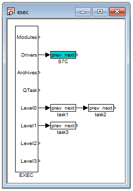
There is one block which must be added to the project to include the driver. A block of type IODRV renamed to S7C and connected to the Drivers output of the main EXEC block. The name of this block (S7C, see Fig. 2.1), is the prefix of all input and output signals provided by this driver. The three most important parameters are:
- module – name of the module linked to the driver, in this case S7Drv – the name is CASE SENSITIVE!
- classname – class of the driver, which defines the role of the target device:
- S7cDrv – for Client mode (emulation of PG)
- S7sDrv – for Server mode (emulation of PLC)
The name is CASE SENSITIVE!
- cfgname – name of the driver configuration file (*.rio, REXYGEN Input/Output), which is discussed in chapter 3
The name of this block (S7C, see Fig. 2.1), is the prefix of all input and output signals provided by this driver.
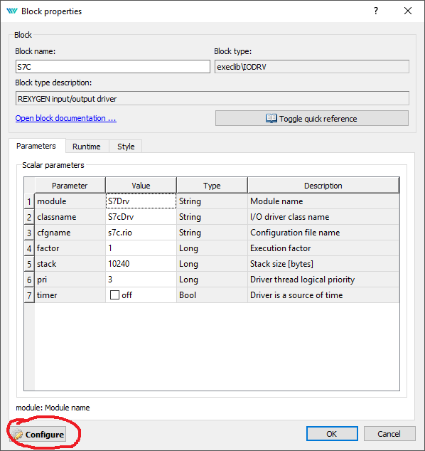
The above mentioned parameters of the IODRV function block are configured in the REXYGEN Studio program as shown in Figure 2.2. The Configure button opens the configuration dialog of the S7Drv driver, which is described in chapter 3.
The Client mode of the S7Drv driver supports the so-called synchronized execution of communication and control tasks. This can be achieved by using the TIODRV function block instead of the IODRV block. The parameters are the same, only the TIODRV block provides the Tasks output, which can be used for connecting IOTASK function block. The parameters are analogous to the TASK block. In this mode the driver reads all inputs first, executes the task defined by the IOTASK block and afterwards sets all outputs and waits for the next period. It is necessary to take into account that in the case of communication failure the IOTASK will not be executed until the communication timeout expires. This approach is therefore applicable mainly for communication periods longer than 10 seconds.
Chapter 3
Driver configuration
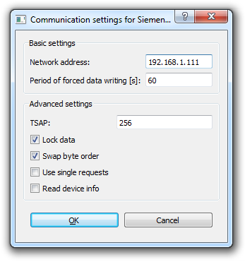
The driver configuration consist in fact only of setting the IP address of the device to communicate with. There are few additional options mainly for debugging, the default values should be used in standard situations. Parameter TSAP depend on SIMATIC configuration, but default value is:
TSAP = (256*<ConnectionType>)+(32*<Rack>)+<Slot>
where <ConnectionType> could be 1 (used by PG), 2 (used by OP), 3 (generic purpose); <Rack> and <Slot> are both zero for module, where comunication cable is connected (e.g. if comunication cable is pluged into comunication module like CP 343-1 and reading data from processor module is required, <Slot> and therefore TSAP, must be changed).
3.1 Connecting the inputs and outputs in the control algorithm
The inputs and outputs of the driver must be interconnected with the individual tasks (.mdl files). The individual tasks (QTASK or TASK blocks) are connected to the QTask, Level0,…, Level3 outputs of the main EXEC block. Use the blocks depicted in Fig. 3.2 to interchange data between the control algorithm and the S7Drv driver.
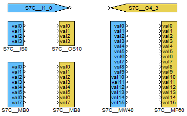
The From block allowing the user to read one input signal has the Goto tag set to S7C__<IN>. The Goto block allowing the user to set one output signal has the Goto tag set to S7C__<OUT>, where <IN> and <OUT> are strings referring to the so-called emphobject dictionary (see below). All the strings used for accessing data provided or accepted by the driver always have the S7C prefix right at the beginning of the tag mandatory followed by two _ characters (underscore).
The use of multi-input/output blocks is recommended to preserve bandwidth. See the function block reference manual [3] for details about the INQUAD, INOCT, INHEXD, OUTQUAD, OUTOCT and OUTHEXD blocks.
The rest of the input or output string reference is interpreted by the driver. The syntax follows the IEC 61131-3 recommendation and also the STEP7 syntax, the only difference is using the underscore character instead of dots. Therefore the syntax can be:
- <area><type><index>
- <area><index>
- <area><index>_<subindex>
- <area><type><index>_<subindex>
The <area> string in the above notation can be:
- M – memory flag
- I – input
- O – output
- D – data block (format no. 4)
- T – timer (format no. 2)
- C – counter (format no 2)
Similarly the <type> string has the following options:
- B – Byte, U8 (0…255)
- W – Word, U16 (0…65535)
- X – Word, but swapped byte order (useful for bitstring variable)
- D – DWord, U32 (0…4294967295)
- E – DWord, but swapped byte order
- S – Short, I16 (-32768…32767)
- T – Short, but swapped byte order
- L – Long, I32 (-2147483648…2147483647)
- M – Long, but swapped byte order
- I – Integer, see type long
- F – Float, F32 (-3.4E+38…3.4E+38)
Finally the <subindex> is a number defining the object in the object dictionary, whose value is read or written.
It is possible to read/write additional auxiliary signals of the given object. This can be achieved by appending the following strings:
- _Value – allias for basic signal value
- _RE – read enable
- _WE – write enable
- _WF – write force
- _Fresh – number of seconds since the last valid value was read (read-only)
- _Area – allow change area code of the object (expert only)
- _Index – allow change index (offset) of the object (expert only)
- _IndexDB – allow change Datablock number of the object (expert only)
The driver supports multi-flags, therefore it is possible to read/write several signals at once. See the (INQUAD, OUTQUAD, INOCT, OUTOCT and INHEXD, OUTHEXD) function blocks as displayed in Figure 3.2. In this case the block name references the first object and the signals are mapped to this object and the consecutive ones (groups of 4, 8 or 16). This preserves communication bandwidth and also clarity of the algorithm.
Chapter 4
Implementation details
Additional information about the use and implementation of the S7Drv driver in the REXYGEN system is gathered in this chapter.
- In PLC world the dot is used as the delimiter when referencing binary signals (e.g. M2.3). This is not possible in the REXYGEN system and therefore the underscore character is used.
- Special references to memory areas are implemented for LOGO devices. The <area> string has these additional options to correlate with the LOGO notation: Q<index> for relay outputs, AI<index> for analog inputs, AM<index> for analog memory flags, AQ<index> for analog outputs.
- LOGO uses the I, Q and M areas only for Boolean signals. Analog signals are in special
areas (area code):
16 NI 17 NQ (read-only) 18 AI 19 AQ 20 AM 21 NAI 22 NAQ (read-only)
Chapter 5
Troubleshooting
In the case that the diagnostic tools of REXYGEN (e.g. Watch mode in the REXYGEN Studio) report unexpected or incorrect values of inputs or outputs, it is desirable to test the functionality outside the REXYGEN system. Also double check the configuration – the most common problems include:
- The Siemens device is in STOP mode.
- Networking/IP address conflict.
- Simultaneous writing to one location from both the Siemens PLC algorithm and the REXYGEN control algorithm.
- Mismatch between little-endian and big-endian implementation. It is possible to swap byte order in the configuration dialog of the driver.
In the case that the given input or output works with other software tools and does not work in REXYGEN, report the problem to us, please. E-mail is preferred, reach us at support@rexygen.com. Please include the following information in your description to help us process your request as soon as possible:
- Identification of the REXYGEN system you are using. Simply export it to a file using the REXYGEN Studio program (Target Licensing Export).
- Short and accurate description of your problem.
- The configuration files of the REXYGEN system (.mdl files) reduced to the simplest case which still demonstrates the problematic behavior.
Bibliography
[1] Davide Nardella. Snap7 - Step7 Ethernet Communication Suite. http://snap7.sourceforge.net, 2015.
[2] REX Controls s.r.o.. Getting started with REXYGEN on Debian, 2020. .
[3] REX Controls s.r.o.. Function blocks of REXYGEN – reference manual, 2024. .
Documentation reference number: 17331
2025 © REX Controls s.r.o., www.rexygen.com