Getting started with REXYGEN on UniPi v1.1
User guide
2022-11-22
Plzeň (Pilsen), Czech Republic
Contents
1.1 Features of the REXYGEN system
1.2 Structure of the REXYGEN system
1.3 Programming in the REXYGEN system
1.4 Main components of the REXYGEN system
1.4.1 REXYGEN Studio – the development environment
1.4.2 REXYGEN HMI Designer
1.4.3 REXYGEN Compiler
1.4.4 RexCore
1.4.5 REXYGEN Diagnostics
2 Installation of REXYGEN development tools
2.1 Windows 7/8/10
2.1.1 Installation procedure
2.1.2 Uninstall procedure
2.2 GNU/Linux
3 Installing the runtime modules of the REXYGEN system on Raspberry Pi
3.1 Installation of REXYGEN runtime
3.1.1 Installation with a script
3.1.2 Manual installation
3.2 Starting the runtime
3.3 Installed files and folders
3.4 Uninstall procedure
4 Configuration, compilation and execution
4.1 Creating a new project
4.2 Compiling and running a project
4.3 Adding a user interface (HMI)
4.4 Ready for interaction with the outer world
5 I/O configuration for the UniPi v1.1
5.1 Physical connections
5.2 Adding inputs and outputs to the project
5.3 Working with I/O signals
5.3.1 Modifications in the project main file
5.3.2 Modifications in the task
5.4 Updating the HMI
5.5 Additional information
5.5.1 Detailed description of the driver
5.5.2 Examples
6 Summary
A Graphical HMI with REXYGEN HMI Designer
A.1 Initializing the HMI design
A.2 Adding the first HMI components
A.3 Linking HMI components with the running algorithm
A.4 Adding more HMI components
A.5 Additional links to the running algorithm
A.6 The final steps
B Licensing of the REXYGEN system
B.1 Obtaining a DEMO licence
B.2 Obtaining a permanent licence
B.2.1 Activation of the permanent licence
Chapter 1
Introduction
The REXYGEN system is a family of software products for automation projects. You can use it in all fields of automation, robotics, measurements and feedback control.
The runtime core of the REXYGEN system turns your Raspberry Pi into a programmable device which will run your algorithms.
1.1 Features of the REXYGEN system
- Graphical programming without hand-coding
- Programming control units on a standard PC or laptop
- User interface for desktop, tablet and smartphone (HMI)
- Wide family of supported devices and input-output units (including UniPi v1.1)
- Industry-proven control algorithms
- Easy integration into business IT infrastructure (ERP/BMS)
- REST API for seamless integration into Industry 4.0 and (I)IoT solutions
1.2 Structure of the REXYGEN system
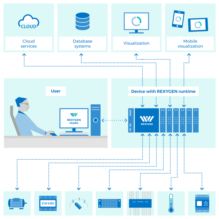
1.3 Programming in the REXYGEN system
The REXYGEN system offers a graphical development environment for programming the algorithms. You can use standard desktop or laptop PC. You create the algorithms from the so-called function blocks. The library includes countless items (timers, comparators, filters, PID controllers and many more).
1.4 Main components of the REXYGEN system
1.4.1 REXYGEN Studio – the development environment
REXYGEN Studio is a developer’s tool which runs on a standard PC with Windows. You create the algorithms using the function block library (The IEC 61131-3 standard defines Function Block Diagram (FBD) as one of the PLC programming techniques.) of the REXYGEN system [1]. The library contains simple comparators and timers as well as advanced blocks for signal processing and feedback control (PID controllers etc.). You compile your project on your PC and run it on your Raspberry Pi.
Once running, you can watch your algorithm in real-time. Just select the signals and function blocks of your interest. You can also obtain detailed hierarchical information about the running algorithm and diagnose the runtime core and execution of your algorithm. You can connect via local network or over the Internet.
1.4.2 REXYGEN HMI Designer
The REXYGEN HMI Designer is another developer’s tool intended for designing graphical user interface (or HMI, Human Machine Interface, if you prefer) for your algorithms. The user interface is included in the project and it is copied to your Raspberry Pi along with the algorithm.
1.4.3 REXYGEN Compiler
The REXYGEN Compiler converts your algorithms into binary code of the REXYGEN system. The compiler is almost invisible for the user, it is invoked from the REXYGEN Studio development environment. The compiler detects and reports possible errors in your algorithms.
1.4.4 RexCore
The RexCore (REXYGEN runtime core) service runs on the target device (Raspberry Pi). Once installed, it runs in the background and therefore it is almost invisible for the user. It handles timing and execution of your algorithms and provides various services. The individual tasks are prioritized and executed using preemptive multitasking. The RexCore service is automatically started at system startup.
RexCore further contains an integrated webserver providing user interface (HMI) and REST API. Chapter 3 deals with installing all the necessary modules on Raspberry Pi.
1.4.5 REXYGEN Diagnostics
With REXYGEN Diagnostics you can diagnose the runtime core and execution of your algorithm. It is an alternative standalone tool for commissioning and diagnostics of control algorithms. All the diagnostic functions are included in REXYGEN Studio, therefore REXYGEN Diagnostics can be considered obsolete. You can connect via local network or over the Internet.
Chapter 2
Installation of REXYGEN development tools
This chapter describes the steps to install and uninstall the development tools of the REXYGEN system on Windows 7/8/10 operating systems. The tools also run on various GNU/Linux distributions using Wine (http://www.winehq.org).
2.1 Windows 7/8/10
The installation package of REXYGEN development tools contains the REXYGEN Studio and REXYGEN HMI Designer development environments, the REXYGEN Compiler compiler and the REXYGEN Diagnostics tool. It also includes the RexCore (REXYGEN runtime core) module for developing and testing purposes.
The installation package can be downloaded from
https://www.rexygen.com/software-download.
The installation process requires the administrator rights on your PC.
2.1.1 Installation procedure
- Run the REXYGEN-X.XX.XX.XXXX-PPP.exe downloaded from
https://www.rexygen.com/software-download. - Select the language and follow the installation wizard.
- Select the target installation folder, the default is
C:\Program Files\REX Controls\REXYGEN X.XX.XX.XXXX. - Afterwards you can select the components to install. The requirements are quite low (approx 400 MB disk space) therefore the Full install option is recommended.
- The following steps are standard and do not require further explanation.
There is no need to restart the system after installation.
2.1.2 Uninstall procedure
The common procedure can be used to uninstall REXYGEN development tools – go to Control panel and choose Install/Uninstall programs.
2.2 GNU/Linux
On various GNU/Linux distributions, you may install the development tools using Wine (http://www.winehq.org) 2.0 or later. Although we test the development tools in Wine regularly, please note that this is meant for experienced users and limited support is provided.
Follow the instructions for installation under Windows 7/8/10 given in section 2.1. The installation is started with wine REXYGEN-X.XX.XX.XXXX-PPP.exe command entered at the console prompt. Some distributions (e.g. Ubuntu) allow running the installator by clicking the REXYGEN-X.XX.XX.XXXX-PPP.exe file.
Chapter 3
Installing the runtime modules of the REXYGEN system on Raspberry
Pi
It is necessary to have a correctly configured Internet connection on your Raspberry Pi running the so-called Raspbian distribution of GNU/Linux (RexCore should also work on any other distribution based on Debian (e.g. Ubuntu).) prior to using this guide. Visit http://www.raspberrypi.org for more information.
3.1 Installation of REXYGEN runtime
REXYGEN runtime may be installed by adding a repository to the source list manually or with a script that automates all the installation tasks.
3.1.1 Installation with a script
Currently, following platforms are supported for full automatic installation: plain Raspberry
Pi, Monarco HAT, UniPi 1.1, PiFace Digital.
For plain Raspberry Pi, run the following commands:
chmod +x rex-install-rpi.sh
sudo ./rex-install-rpi.sh
For Monarco HAT, run the following commands:
chmod +x rex-install-monarcohat.sh
sudo ./rex-install-monarcohat.sh
For UniPi version 1.1, run the following commands:
chmod +x rex-install-unipi1_1.sh
sudo ./rex-install-unipi1_1.sh
For PiFace Digital extension board, run the following commands:
chmod +x rex-install-pifacedigital.sh
sudo ./rex-install-pifacedigital.sh
These scripts always install the stable branch of REXYGEN. The scripts also provide --testing and --next parameters (e.g. sudo ./rex-install-rpi.sh --testing) to install development branches. The "testing" branch contains a REXYGEN version that is to be released soon, but still under testing. The "next" branch contains the current state of a next REXYGEN version under development. Use these options carefully.
3.1.2 Manual installation
Following instructions guide you through installation of REXYGEN runtime on plain Raspberry Pi. See documentation for other platforms for specific installation steps.
- Add REXYGEN public key:
wget -nc https://download.rexcontrols.com/files/key/rex-debian-key.pub
sudo apt-key add rex-debian-key.pub - Add the repository to /etc/apt/sources.list or create a *.list under /etc/apt/sources.list.d/
with the following content:
deb http://download.rexcontrols.com/repositories/debian-rex-2.50/ bullseye non-free
Replace bullseye with buster or stretch if you are still running the older Raspbian distribution. Replace debian-rex-2.50 with debian-rex-2.50-testing or debian-rex-2.50-next to install development branches. The "testing" branch contains a REXYGEN version that is to be released soon, but still under testing. The "next" branch contains the current state of a next REXYGEN version under development. Use these options carefully.
- Update package list:
sudo apt update
- Install REXYGEN runtime:
sudo apt install -y --install-recommends rexygen-runtime
- Perform specific installation steps for your platform (Monarco HAT, UniPi 1.1, PiFace Digital etc.).
3.2 Starting the runtime
Right after the installation, the RexCore runtime module is started automatically in the background as a daemon and it is possible to establish connection between the host PC and the Raspberry Pi using the REXYGEN Studio program. RexCore also automatically runs upon system (re)start.
3.3 Installed files and folders
Please refer to the RexCore user guide [2] for detailed information about the files and folders of the REXYGEN system runtime modules.
3.4 Uninstall procedure
Use the following commands to remove REXYGEN runtime from the operating system:
sudo apt-get autoremove
Chapter 4
Configuration, compilation and execution
The process of creating a control algorithm will be demonstrated on a very simple example with four Boolean variables representing manual switches. In Chapter 5.3, two of them will be replaced by physical inputs of the UniPi v1.1. A software timer will be used for measuring the time when the variables are true (i.e. the switches are in the ON position). A Boolean signal will indicate that the interval of predefined length has elapsed.
4.1 Creating a new project
The project configuration is created using the REXYGEN Studio program. Each project consists of at least two .mdl files. The first file is the main file of the project, which is used for configuration of tasks, drivers, priorities and timing. The other file(s) contain the individual control algorithms (tasks).
First we’ll create the example 0101-01 from scratch (All examples which are part of the installation are marked by an ExampleID. The most up-to-date examples are available with the latest installation of development tools or at https://www.rexygen.com/example-projects/).
Standard approach:
- Run the REXYGEN Studio program. Start with a plain project and select a folder to save the project files in (e.g. D:\GettingStarted).
- The folder will contain two important files:
- myproject_exec.mdl
- myproject_task.mdl
- The myproject_exec.mdl is the project main file. It contains one EXEC block from the
EXEC library. The other block is the TASK block from the same library and it is renamed
to myproject_task to reference the second file of the project (myproject_task.mdl),
which will contain the algorithm (the so-called task).
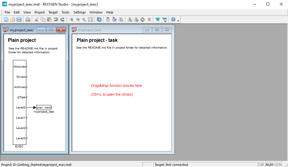
- The task is connected to the Level0 output of the EXEC block and therefore its timing is defined by tick and ntick0 parameters of the EXEC block.
- The EXEC block (and any other block) can be configured by double-clicking on it. A block
parameters and properties dialog appears. The parameters of all blocks of the REXYGEN
system are described in the Help (press the F1 key) and in the Block reference
manual [1].
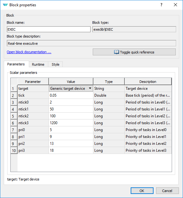
- Note that tick=0.05 and ntick0=2, therefore the task will run each 100 milliseconds (). There is no need to change any parameter at the moment. Close the dialog.
- You can delete all the descriptive texts in project files. These have no effect on the functionality and can be considered programmer’s comments.
- Open Block Library, choose View/Block Library in the menu or use the
 icon from the toolbar.
- By default, the library is in Tree view mode where the blocks are organized in
sublibraries. Their location is always denoted as sublibrary/block, e.g. LOGIC/AND for
the logical AND block in the LOGIC sublibrary. Inside a sublibrary, the blocks are ordered
in alphabetical order.
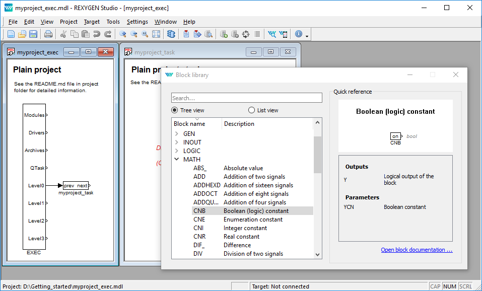
- You can also switch the library to List view mode, where all the blocks are sorted alphabetically, regardless of the sublibrary they belong to.
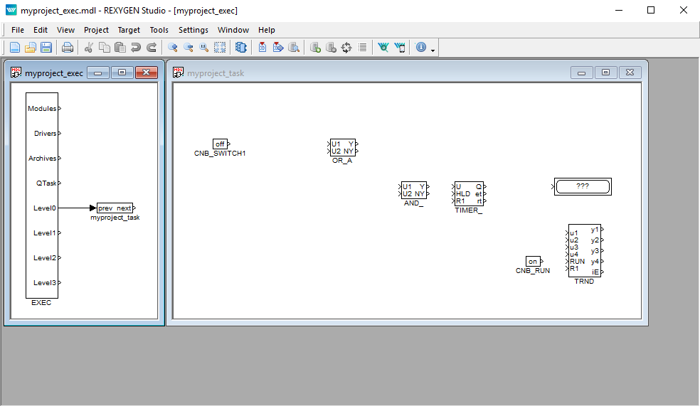
- Locate the following function blocks in the Block Library and drag them to the task
file:
- MATH/CNB – constant of type Boolean. Once dropped, double-click its name and change it to CNB_SWITCH1. Double-click the block and set parameter .
- LOGIC/OR_ – logical OR. Rename it to OR_A.
- LOGIC/AND_ – logical AND.
- LOGIC/TIMER_ – a timer block. Set parameter , .
- INOUT/Display – a display to show values in real-time.
- ARC/TRND – real-time recording. Set parameters , , leave the default values otherwise.
- MATH/CNB – constant of type Boolean, change name to CNB_RUN, set parameter .
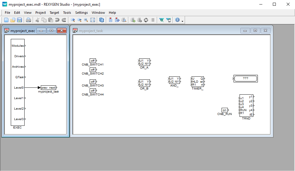
- Duplicate the CNB_SWITCH1 block with right mouse button dragging. Or simply Copy&Paste the block.
- Duplicate the block 2 more times.
- Duplicate also the OR_A block. Rename the duplicate to OR_B.
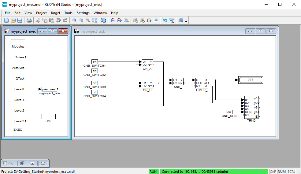
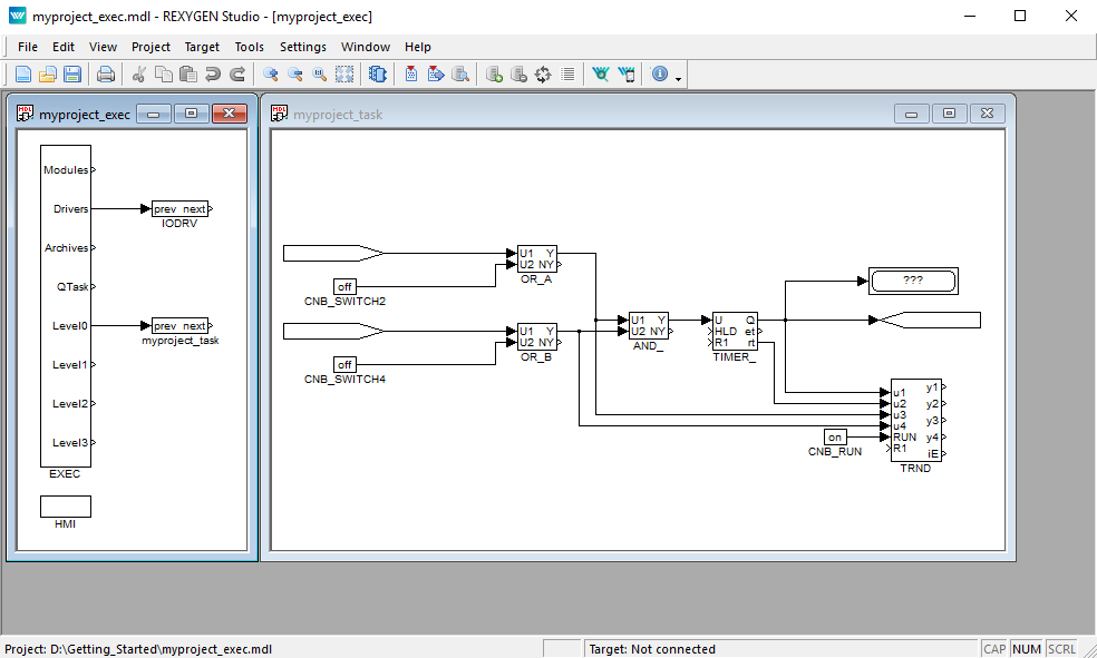
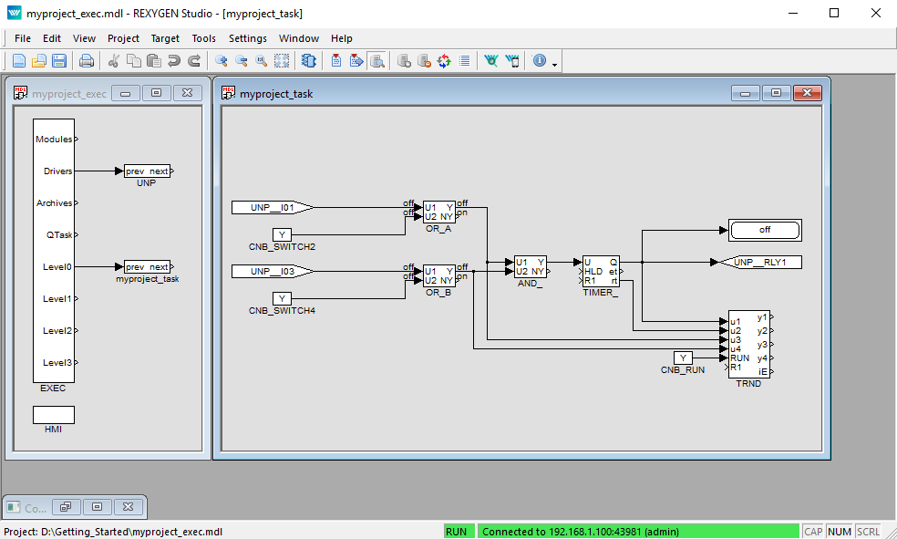
- Connect the blocks as shown below. To connect the blocks, drag the output arrow of one
block to the input arrow of the other block using the left mouse button. The connection
will be established when the line goes bold and green. After releasing the mouse button
you can recognize a successfully connected line by its style. A full line terminated by a
full arrow at the input of the connected block indicates a valid connection. A dashed red
line ending with a thin arrow indicates an unconnected line. New branch of an
existing line can be created by dragging an existing line with the right mouse
button.
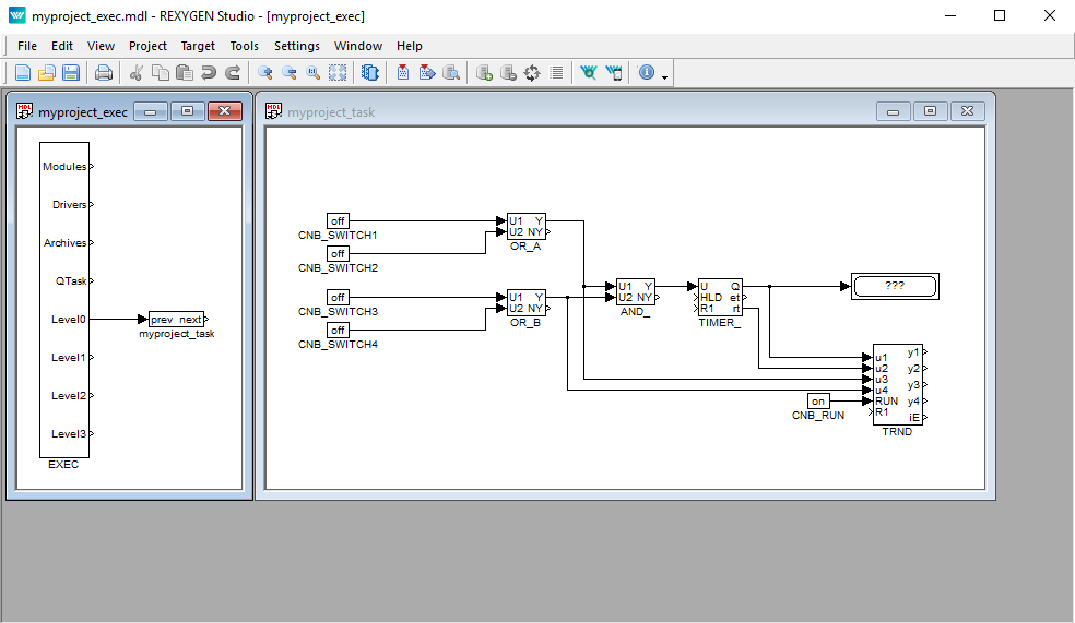
At this moment the executive configuration myproject_exec.mdl and the corresponding myproject_task.mdl file with the algorithm are ready. The algorithm will be evaluated in the direction of the arrows, starting from the source CNB blocks, passing through the OR_, AND_ and TIMER_ blocks and finishing at the Display and TRND blocks.
Congratulations, your first project is ready for compilation!
4.2 Compiling and running a project
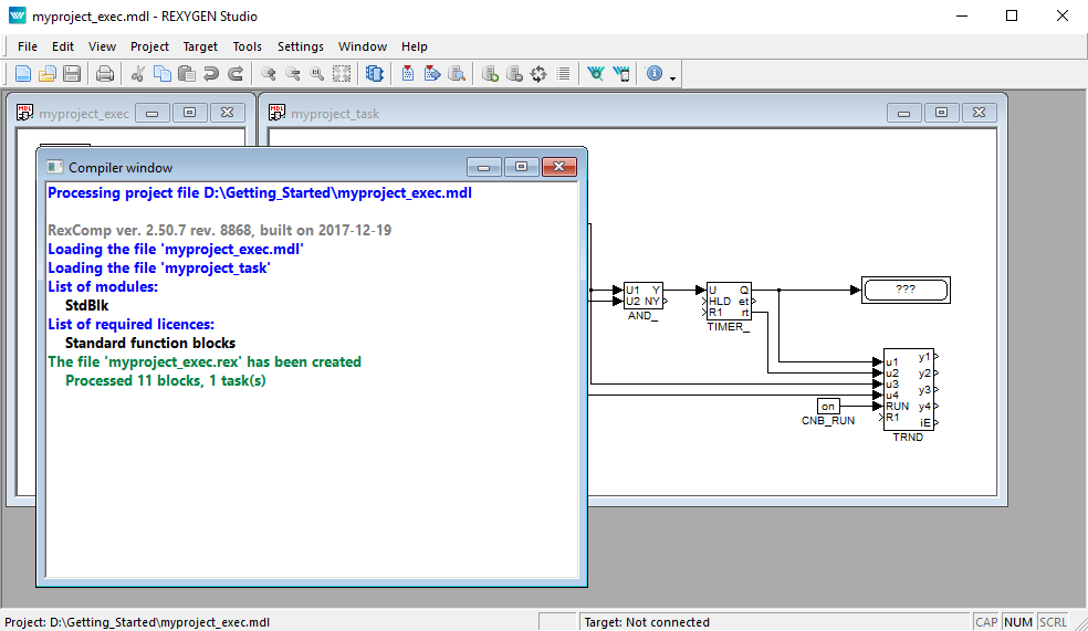
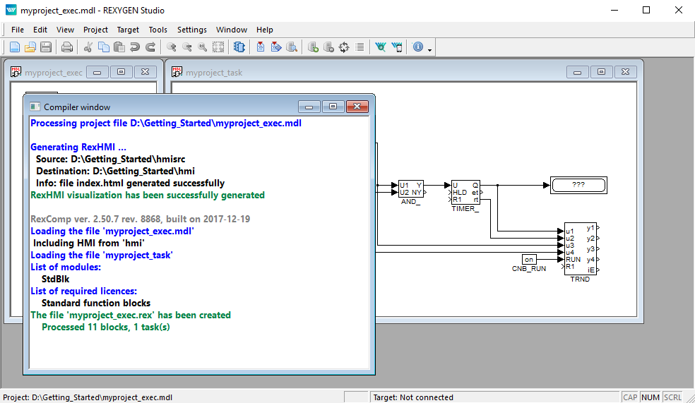
The developed algorithm must be compiled to binary form prior
to deploying. Pick Project/Compile from the menu or use the
 icon from the toolbar. The compiler output is displayed in the Compiler window. If no error is
found, the myproject_exec.rex file is created.
icon from the toolbar. The compiler output is displayed in the Compiler window. If no error is
found, the myproject_exec.rex file is created.
At this moment it is possible to deploy the control algorithm to the target platform. Use
Project/Compile and Download in the menu or click the Compile and Download
icon  for this purpose. A dialog for defining the target device appears upon successful compilation.

Enter the IP address of your Raspberry Pi in the Target field.
Enter REXYGEN login and password. The default user is admin and there is no password by default. Leave the other elements intact and click Download.
If there is no licence on your Raspberry Pi, you need to get one first. You can get a DEMO licence for free. See Appendix B for details and come back afterwards.
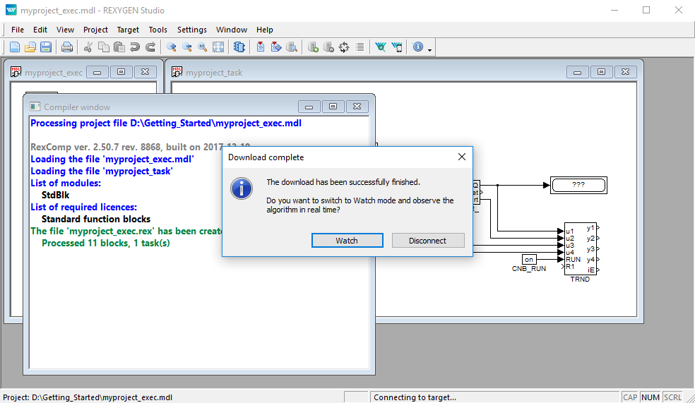
As soon as the download is complete it is possible to switch the REXYGEN Studio application to the so-called Watch mode and watch the control algorithm in real-time – click Watch.
In the Watch mode, the background of all files goes gray and you cannot move or delete any blocks or connections. Right-click the TIMER_ block and select Watch selection in the menu to watch the inputs and outputs of the timer.

You can do the same with the OR_ and AND_ blocks (or any other selection).
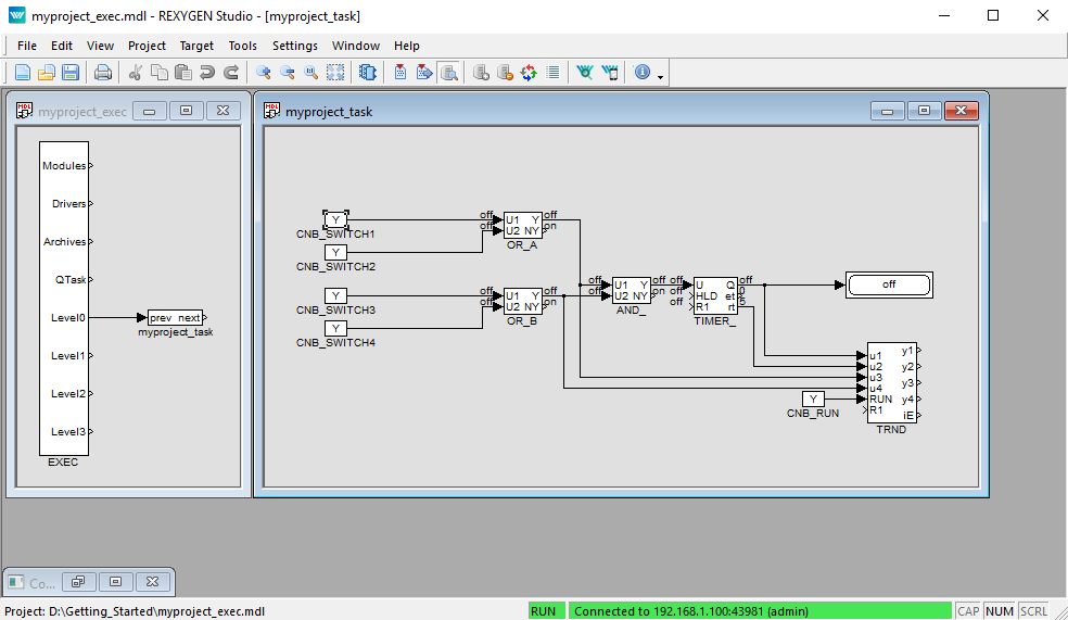
Now it is possible to double-click the CNB_SWITCH1 block and change the Boolean variable to (tick the checkbox and click OK). Once you do the same with the CNB_SWITCH3 block, the outputs of both OR blocks are on and the Y output of the AND_ block goes on and the TIMER_ starts to count down. Observe the rt output. (Do not get confused by the default 1 second refresh rate of the Watch mode. The algorithm on the target device runs each 100 milliseconds as mentioned earlier.) Once the timer reaches zero, its output Q is set to on and it remains on as long as the U input is on.
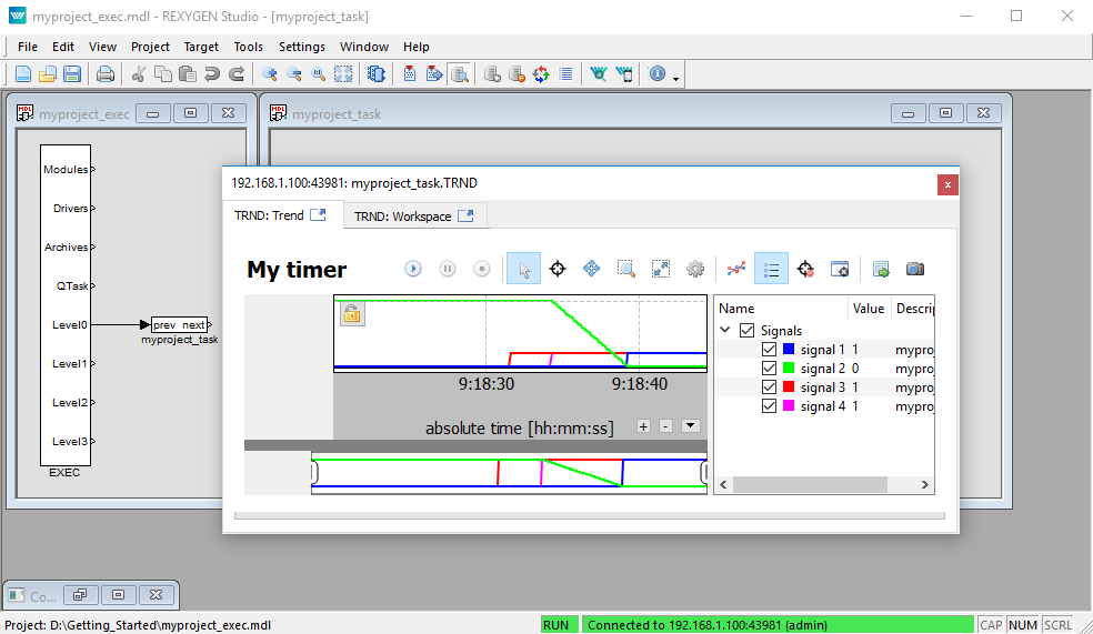
You can double-click the TRND block to see the signals in a real-time graph. The red line is the output of the OR_A block, the magenta line is the output of the OR_B block, the green line is the remaining time of the timer and the blue line is the Boolean output of the timer.
Try turning the CNB blocks off and change the pt parameter of the TIMER_ block. Afterwards turn the CNB blocks on again and observe the signals in the TRND block again. As you can see, you can modify any parameter in real-time, which allows you to fine tune your algorithm.
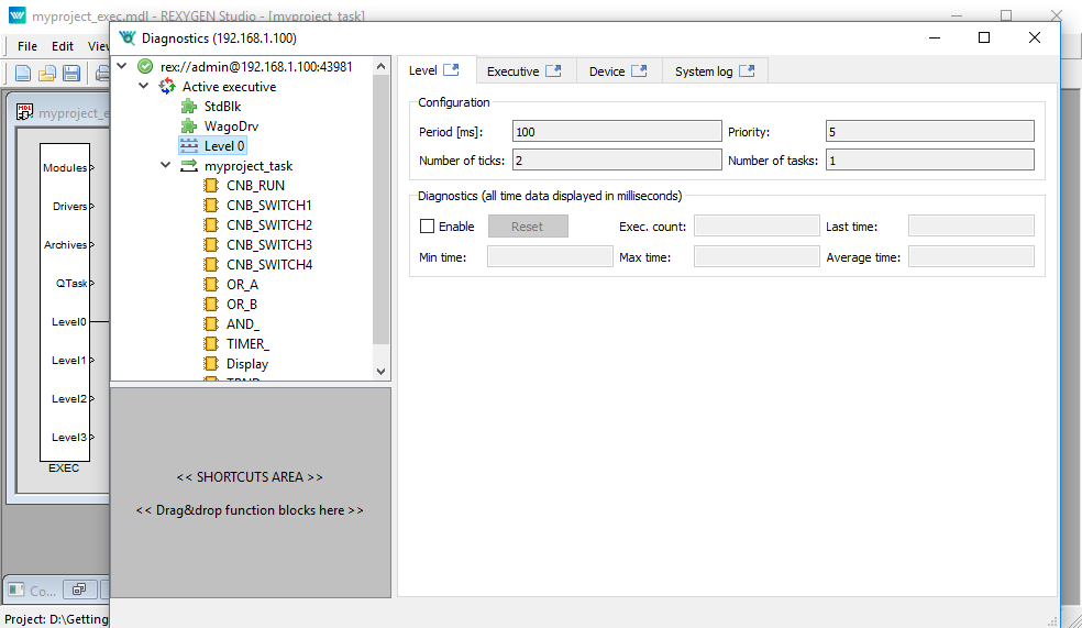
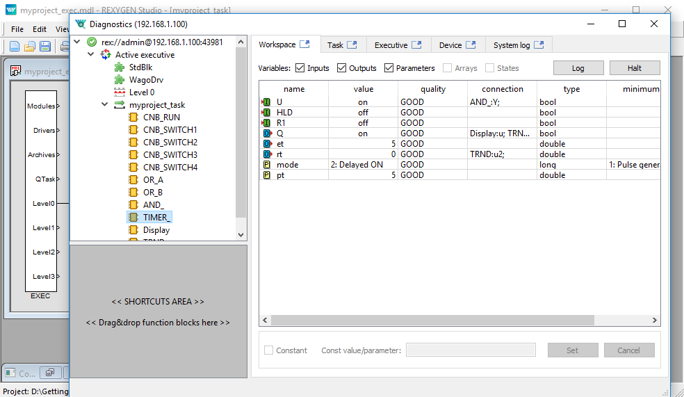
It is also possible to open a Diagnostics view of the algorithm. Pick Target/Diagnostics from the menu or click
the  icon and you will see the algorithm in a tree view which allows you to monitor the control
algorithm in full detail. You can verify that the sampling rate of your algorithm is
indeed 100 milliseconds. You can also adjust parameters of individual function blocks,
which has the same effect as modifying them directly in the Block properties dialog.
icon and you will see the algorithm in a tree view which allows you to monitor the control
algorithm in full detail. You can verify that the sampling rate of your algorithm is
indeed 100 milliseconds. You can also adjust parameters of individual function blocks,
which has the same effect as modifying them directly in the Block properties dialog.
Note: There is also a standalone diagnostics program called REXYGEN Diagnostics. Click the REXYGEN Diagnostics
icon  and confirm the IP address of the target platform.
Now you can switch REXYGEN Studio back to the Development
mode. You can do so by deactivating the Watch mode (use the
 icon). You are offered synchronization of the changed parameters with the source files of the
project, choose No at this moment.
icon). You are offered synchronization of the changed parameters with the source files of the
project, choose No at this moment.
All changes made while in the Watch mode are not permanently stored in the target device (unless you decide so, see [3]). Upon restarting the RexCore runtime module the algorithm will start with the parameters defined in the project source files, which were valid when compiling and downloading the algorithm to the target device. To apply the changes permanently, you have to transfer the changes to the source files and Compile and download the project one more time which defines new startup values.
4.3 Adding a user interface (HMI)
The next step in developing a control algorithm is its user interface, or HMI, Human-Machine-Interface. It allows anyone (even those who are not familiar with the REXYGEN system) to interact with the algorithm. The HMI of the REXYGEN system relies on modern web-based technology and the HMI is therefore accessible via web browser on desktop PC, tablet or smartphone.
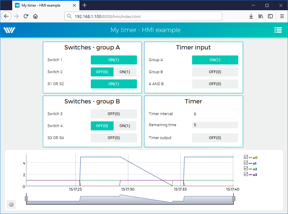
In this tutorial, a simple HMI will be created using the so-called WebBuDi technology. It provides very simple indicators and input elements to interact with the control algorithm via a web page (Web Buttons and Displays).
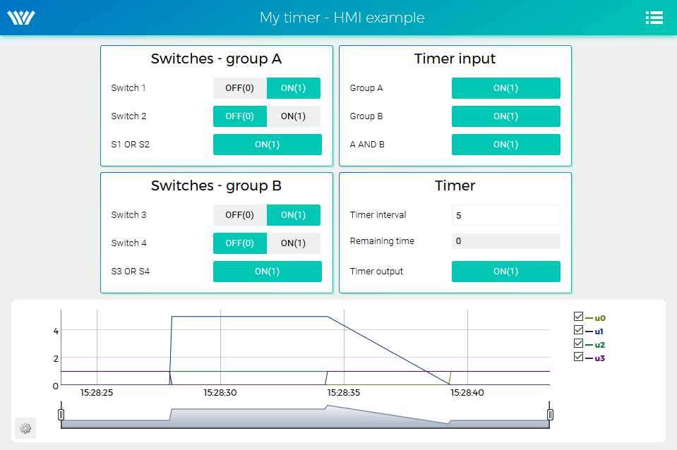
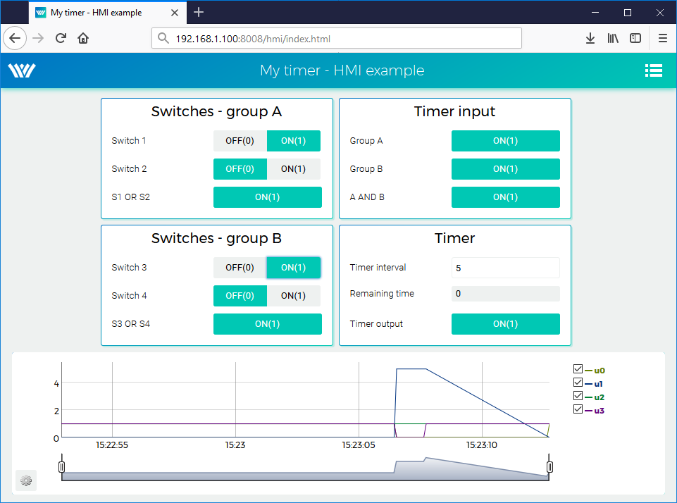
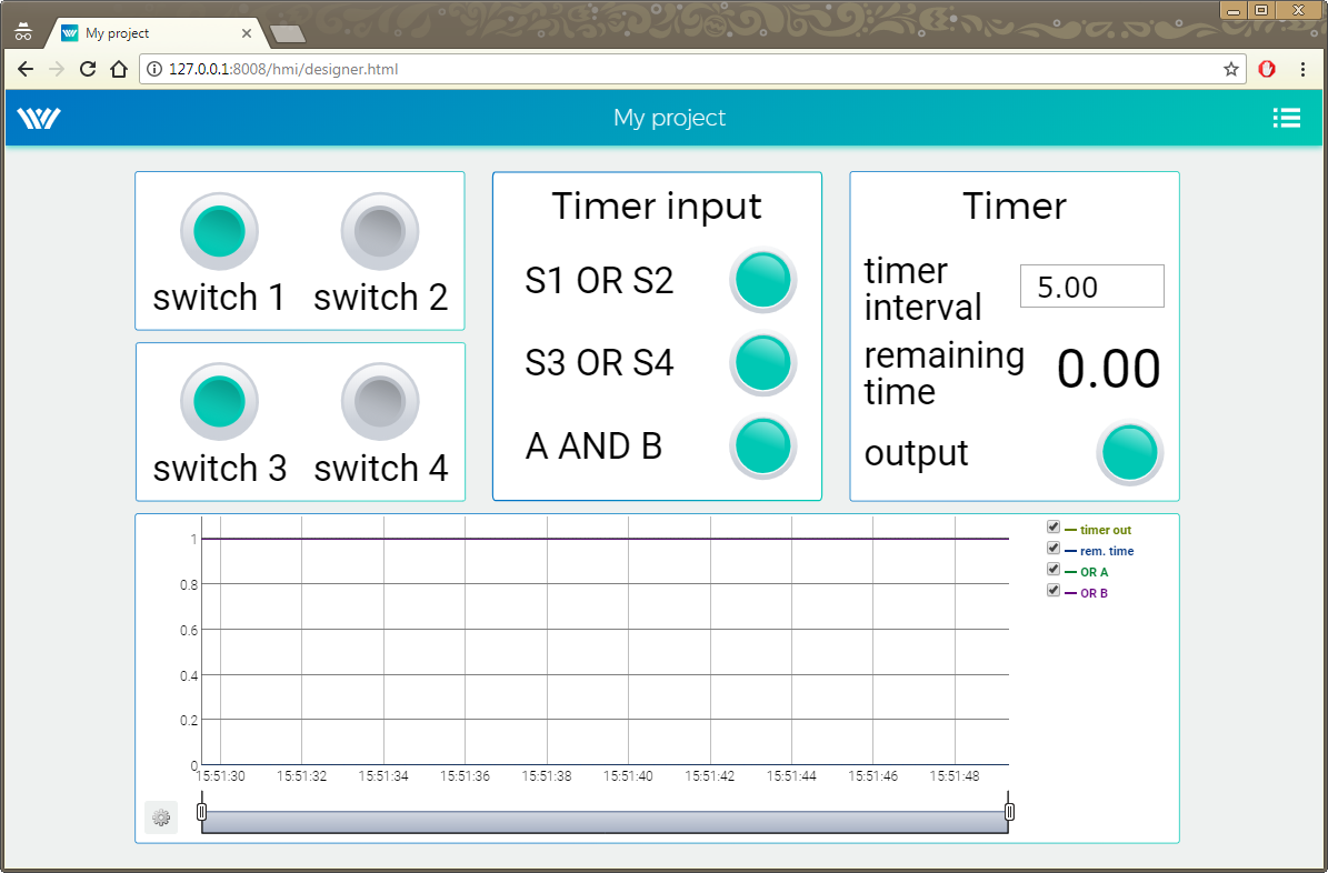
The steps to create the HMI are described below. This is how the HMI will look like in the end:
- In the folder with the project files, create a hmisrc subfolder. Inside this folder, create a
file named index.hmi.js and edit it with your favorite text editor. The content should
be the following:
REX.HMI.init = function(){
//Indicators and virtual switches - group A
var switchesA = {
column: 1,
title: 'Switches - group A',
rows: [
{type: 'DW', alias: 'switch1', desc: 'Switch 1',
cstring: 'myproject_task.CNB_SWITCH1:YCN'},
{type: 'DW', alias: 'switch2', desc: 'Switch 2',
cstring: 'myproject_task.CNB_SWITCH2:YCN'},
{type: 'DR', alias: 'S1orS2', desc: 'S1 OR S2',
cstring: 'myproject_task.OR_A:Y'},
]
};
REX.WebBuDi.addSection(switchesA);
//Indicators and virtual switches - group A
var switchesB = {
column: 1,
title: 'Switches - group B',
rows: [
{type: 'DW', alias: 'switch3', desc: 'Switch 3',
cstring: 'myproject_task.CNB_SWITCH3:YCN'},
{type: 'DW', alias: 'switch4', desc: 'Switch 4',
cstring: 'myproject_task.CNB_SWITCH4:YCN'},
{type: 'DR', alias: 'S3orS4', desc: 'S3 OR S4',
cstring: 'myproject_task.OR_B:Y'},
]
};
REX.WebBuDi.addSection(switchesB);
//Timer input
var timerInput = {
column: 2,
title: 'Timer input',
rows: [
{type: 'DR', alias: 'inputA', desc: 'Group A',
cstring: 'myproject_task.AND_:U1'},
{type: 'DR', alias: 'inputB', desc: 'Group B',
cstring: 'myproject_task.AND_:U2'},
{type: 'DR', alias: 'AandB', desc: 'A AND B',
cstring: 'myproject_task.AND_:Y'},
]
};
REX.WebBuDi.addSection(timerInput);
//Timer settings and status
var timer = {
column: 2,
title: 'Timer',
rows: [
{type: 'AW', alias: 'interval', desc: 'Timer interval',
cstring: 'myproject_task.TIMER_:pt'},
{type: 'AR', alias: 'rt', desc: 'Remaining time',
cstring: 'myproject_task.TIMER_:rt'},
{type: 'DR', alias: 'timerQ', desc: 'Timer output',
cstring: 'myproject_task.TIMER_:Q'},
]
};
REX.WebBuDi.addSection(timer);
//Add real-time trend
REX.HMI.Graph.addTrend({cstring: 'myproject_task.TRND'});
REX.HMI.Graph.setMaxBufferSize(200);
// Change title of the page
REX.HMI.setTitle('My timer - HMI example');
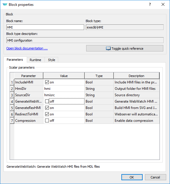
} - This file will be processed when compiling the project. However, it is necessary to add
the EXEC/HMI block into the project main file first.
- Double-click the HMI block to edit its parameters. Set
and confirm. WebWatch is another type of HMI, which you do not need at the
moment. See [4] for details, it is a very interesting tool for developers and
technicians.
- The HMI is now an integral part of your project. Compile the project again and you will
see that the compile log contains more information. The index.html file is generated
from the source index.hmi.js file. All the HMI files are generated into the hmi subfolder
(HTML, JS and CSS files) and included in the resulting binary myproject_exec.rex
file.
- After you download the project to the target device, you can access the HMI via web
browser. Go to menu Target/Web Interface which will open the webpage. Remember the
default login credentials: admin with no password.
- You can toggle the switches and observe the results. The virtual switches are linked to the individual CNB function blocks therefore the effect is the same as toggling the values directly in REXYGEN Studio.
- You can also change the timer setting and shorten or lengthen the interval.
- See [4] for detailed information about WebBuDi elements and possible customization (colors, backgrounds etc.).
- The default URL address is http://192.168.1.100:8008/hmi/index.html (replace 192.168.1.100 with the IP address of your UniPi v1.1).
- The default port of the webserver (8008) can be changed in RexCore settings. See [2] for details.
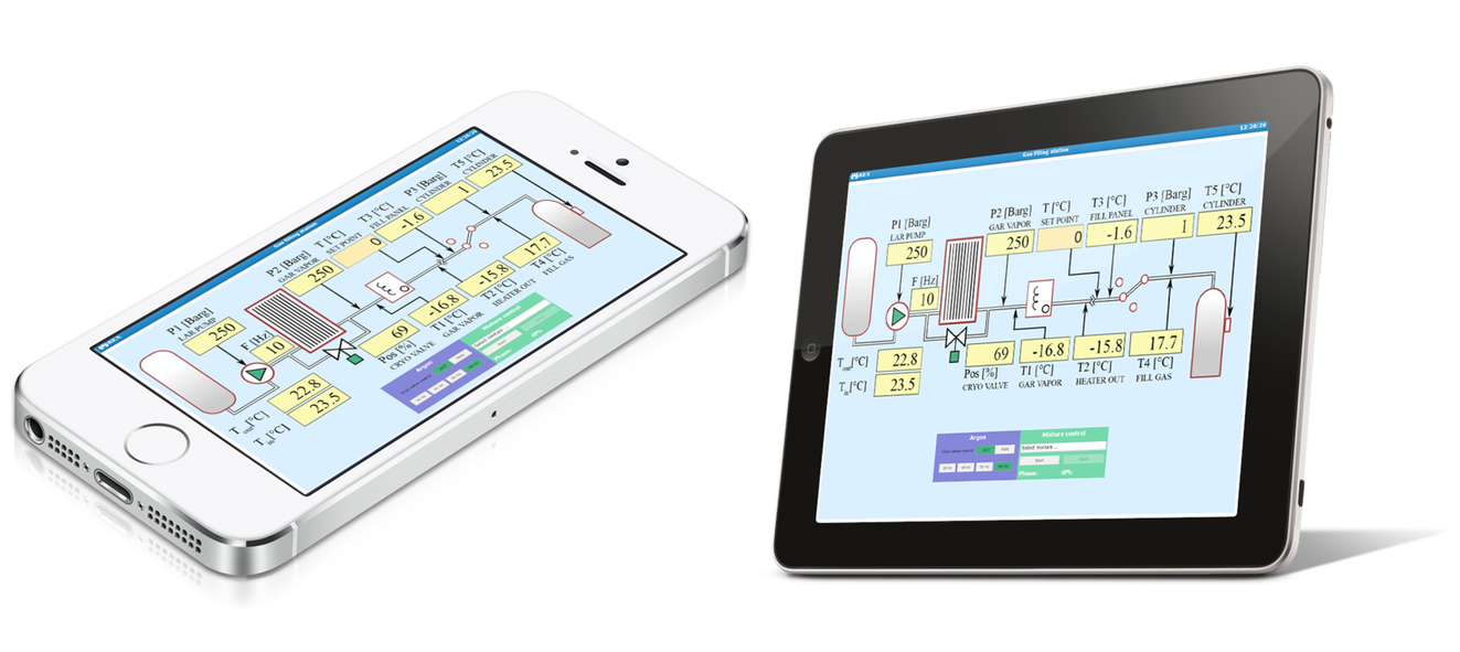
Please note that there is also a program called REXYGEN HMI Designer, which allows you to create graphical user interfaces. Appendix A of this guide shows the steps to create a basic graphical interface. A more complex HMI is shown below solely for inspiration purposes.
4.4 Ready for interaction with the outer world
Well done! You have created the example 0101-01 from scratch (All examples which are part of the installation are marked by an ExampleID. The most up-to-date examples are available with the latest installation of development tools or at https://www.rexygen.com/example-projects/). You have learned the basic workflow for developing and running your algorithms using the REXYGEN system, which is the same for all platforms. Now it’s time to add the so-called input-output drivers so that the algorithm can interact with sensors, actuators and external data.
Chapter 5
I/O configuration for the UniPi v1.1
The previous chapter illustrated the process of creating a control algorithm in the REXYGEN system and deploying it to the target device. But so far, the algorithm does not interact with the outer world, it is not connected to any physical signal (or external data).
We will use the input and output signals of the UniPi v1.1 for interaction with the real world.
As mentioned in Chapter 4, two physical switches will be connected as inputs and a software timer will control one output signal. In other words, this chapter is devoted to advancing from the generic example 0101-01 to example 0122-01 for the UniPi v1.1.
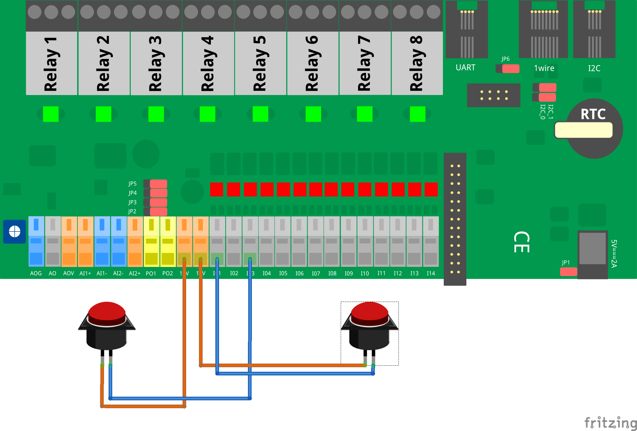
5.1 Physical connections
Connect the switches as shown below.
5.2 Adding inputs and outputs to the project
Now when we have everything wired up, it’s time to include the physical signals into the algorithm. You need to expand your project main file with 2 additional function blocks to access the inputs and outputs from the control algorithm in your project. Insert the EXEC/MODULE and EXEC/IODRV blocks from the Block library and attach them to the EXEC block as shown below.
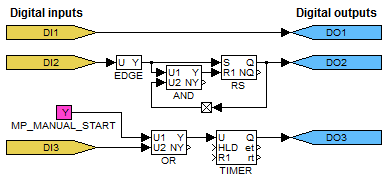
In the task file, delete the CNB_SWITCH1 and CNB_SWITCH3 blocks and replace them with INOUT/From blocks. These will be the input signals. Also add one INOUT/Goto block, which will serve as an output and which will be controlled by the timer. You already know that a new branch of a line is created by right-button dragging, don’t you?
5.3 Working with I/O signals
5.3.1 Modifications in the project main file
Now we tell the compiler to use the UniPi v1.1 I/O driver. To do this, edit the IODRV block parameters. Link the IODRV block with the RPiDrv module by setting
- – CASE SENSITIVE!
Continue editing the IODRV block parameters. For UniPi v1.1 set the following:
- – CASE SENSITIVE!
- Leave the cfgname parameter blank.
- Leave the other parameters intact.
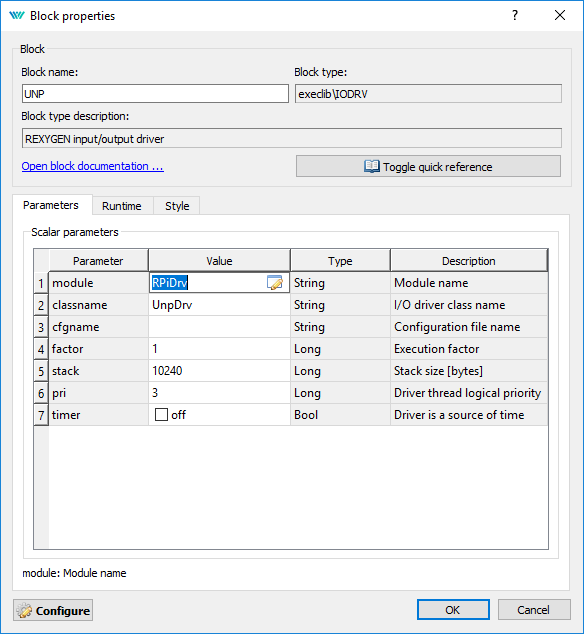
As the final step, rename the IODRV block to UNP, which will serve as a prefix for all I/O signals of this driver.
The executive of the REXYGEN system is configured, your project should look like this:

5.3.2 Modifications in the task
In the task double-click the input flag and set .Note the UNP prefix and two underscore characters. The first physical switch will be connected to digital input I01.
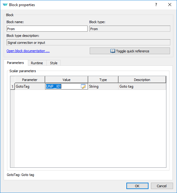
The second physical switch will be connected to I03 (UNP__IO3) and relay 1 will serve as the output signal (UNP__RLY1).
Similarly for other I/Os we could use the following flags:
- Goto, UNP__RLY8 – relay output 8
- From, UNP__I06 – digital input 6
- From, UNP__AI1 – analog input 1
A detailed description of the I/O driver for UniPi v1.1 is available in a separate manual [5].
Your project should now look like this:

After compiling the project and downloading it to the Raspberry Pi the control algorithm interacts with the physical world. Again it is possible to switch to Watch mode and observe the signals in real-time or analyze the trends of signals. Flip the physical switches and watch the signals.
5.4 Updating the HMI
It is also necessary to update the HMI. The CNB_SWITCH1 and CNB_SWITCH3 blocks are no longer present in the algorithm. Moreover, we need to replace virtual input elements (DW) with indicators (DR). Therefore open the index.hmi.js file and replace
cstring: 'myproject_task.CNB_SWITCH1:YCN'},
with
cstring: 'myproject_task.OR_A:U1'},
Similarly for switch no. 3, replace
cstring: 'myproject_task.CNB_SWITCH3:YCN'},
with
cstring: 'myproject_task.OR_B:U1'},
Save the file, compile and download the project again and open the web interface. Push the two physical switches and wait until the timer triggers the output. Alternatively, you can still use the virtual switches. This demonstrates that you can combine physical and virtual input elements.
5.5 Additional information
5.5.1 Detailed description of the driver
A detailed description of the IO driver for UniPi v1.1 is available in a separate manual [5].
5.5.2 Examples
Example projects and a set of all supported I/O flags are included in the installation package
of the REXYGEN system development tools. In REXYGEN Studio, go to menu File
Start from an Example Project and select one of the UniPi v1.1 examples. As
mentioned earlier, the most up-to-date information about examples are available
at
https://www.rexygen.com/example-projects/
Chapter 6
Summary
Congratulations, you have created the example 0122-01 from scratch! You have learned how to develop, compile and run your algorithms on the Raspberry Pi. The interaction with sensors and actuators is provided via input-output driver of the REXYGEN system, which you have learned to configure and use.
You have achieved quite a lot in a relatively short time, haven’t you? The purpose of this guide was to quickly show you the basic steps and tools for developing a project.
Now it’s time to focus on your own project and keep learning on the go. There are function blocks which are much more powerful than the ones mentioned in this guide, there are many inspiring example projects, there are additional I/O drivers which you can use to expand the scope of your project, there are many ways to exchange data with external systems and devices, etc.
Remember that whenever you have some achievement to share, we will be happy to hear from you. And whenever you encounter any difficulties, we will be happy to help. You can reach us at support@rexygen.com.
Appendix A
Graphical HMI with REXYGEN HMI Designer
Chapter 4 describes the creation of a simple WebBuDi user interface. The REXYGEN development tools also contain the REXYGEN HMI Designer program which is a tool for designing custom graphical visualizations from predefined components (Definition of custom components is also possible but it requires a bit of Javascript coding.). The REXYGEN HMI Designer is based on the well-known open-source vector editor InkscapeTM https://inkscape.org/en/.
In this chapter we’ll develop an alternative HMI for the example 0101-01. Just like in the case of the WebBuDi user interface, the SVG file created with REXYGEN HMI Designer will serve as a source file which will become a part of your REXYGEN project. During compilation of the project the SVG file will be processed and converted to HTML, JS and CSS files.
A.1 Initializing the HMI design
After launching the REXYGEN HMI Designer from Start Menu you will find a clean page. The first thing to do is to initialize the new visualization. The HMI is configured via the REXYGEN HMI extensions. Navigate to Extensions REXYGEN HMI Edit HMI Config in the menu.
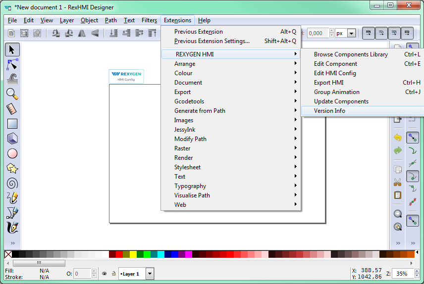
This extension adds a special component which contains general settings of the HMI. Close it with the OK button for now.
In order to include the HMI during the REXYGEN project compilation, the file name has to end with .hmi.svg. Save the file as e.g. designer.hmi.svg to the hmisrc subfolder of your project. Use the standard File Save as menu.
Note: If you want to replace the WebBuDi interface with the REXYGEN HMI Designer interface just delete the index.hmi.js and save the HMI as index.hmi.svg.
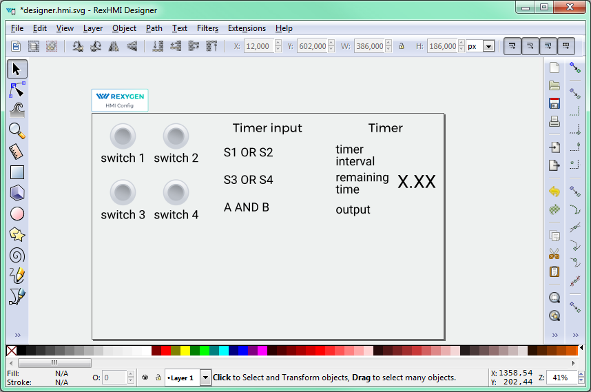
A.2 Adding the first HMI components
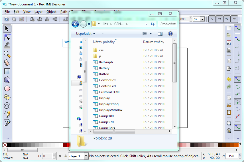
Now we will add some displays and inputs. The REXYGEN HMI Designer contains a library of components which you can use to build your HMI. The library is available through Browse Components Library extensions. Navigate to Extensions REXYGEN HMI Browse Components Library (Ctrl+L). It will open the explorer window with several folders. Open the GENERAL folder and drag&drop the Display to the drawing. The display will be used as an indicator of the remaining time in the TIMER function block.
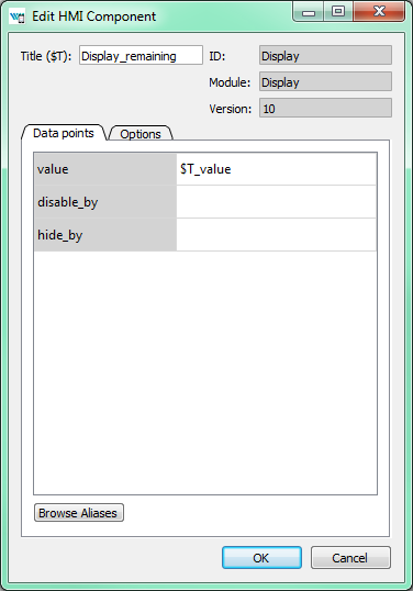
For configuration of the display settings select the display by mouse click on top of it and use the Edit Component extension from Extensions REXYGEN HMI Edit Component (Ctrl+E). When the configuration dialog is opened you can change the Title to Display_remaining. The Edit Component dialog has two tabs: Data points and Options.
The Data points tab contains three items defining the behavior and animations of the component. Each data point contains an alias, which is in fact a connection to live data from the REXYGEN algorithm.
- value – The value to display.
- disable_by – If true the display is disabled and data are no longer updated.
- hide_by – If true the display is hidden.
The value property contains $T_value. The $T will be later automatically substituted by the Title of the component, resulting in the Display_remaining_value alias. The disable_by and hide_by data points are optional. Leave them blank at the moment.
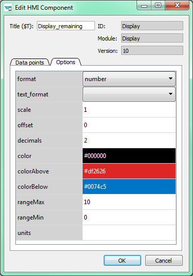
The Options tab contains several properties which are specific for the Display component.
You can find the description of each component and property in [4]. Leave the default values
for now and press OK.
Note: Each component is in fact one SVG group with unique content. You can copy the
components all over the screen using copy (Ctrl+C) and paste (Ctrl+V) approach.
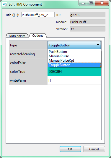
Now we will add controls for all the switches (CNB blocks). All of them will be controlled using the PushOnOff components. Add them from the library. Select the first PushOnOff and open the editor dialog Extensions REXYGEN HMI Edit Component (Ctrl+E). Change the title to PushOnOff_SW_1 and select the Options tab. Select the ToggleButton item in the type property list. Close the Edit Component dialog using OK button. Copy-paste the button three times and remember to change the titles to PushOnOff_SW_2, PushOnOff_SW_3, PushOnOff_SW_4).
Note: Throughout the REXYGEN HMI Designer you can use double click in Options tab to open the corresponding configuration dialog (color picker, number input, etc.).
Now we have four PushOnOff buttons and one Display and we want to link all components with live data from the target device.
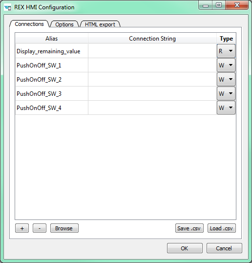
A.3 Linking HMI components with the running algorithm
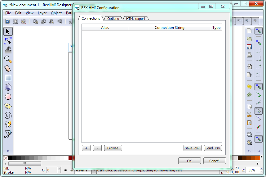
Open the HMI Configuration dialog either using Extensions REXYGEN HMI Edit HMI Config or just unselect all components in the drawing (click outside any component) and press Ctrl+E. The configurator parses all components and creates a list of used Aliases. Each of them should be linked with one signal in the running algorithm. You can either fill in each connection string manually or you can use the Browse function.
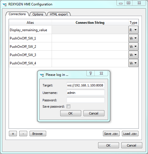
The Browser requires a target device with running algorithm. Make sure the algorithm is running, see Section 4.2. Also the target URL must be set. Press Browse button. The login dialog will be opened. Change Target to 192.168.1.100:8008 (replace 192.168.1.100 with the IP address of your UniPi v1.1). Unless you changed the login credentials, use the default username admin with an empty password. After a successful login the connection tab is expanded with a tree-view of the running algorithm (you have already seen this tree-view in algorithm diagnostics).
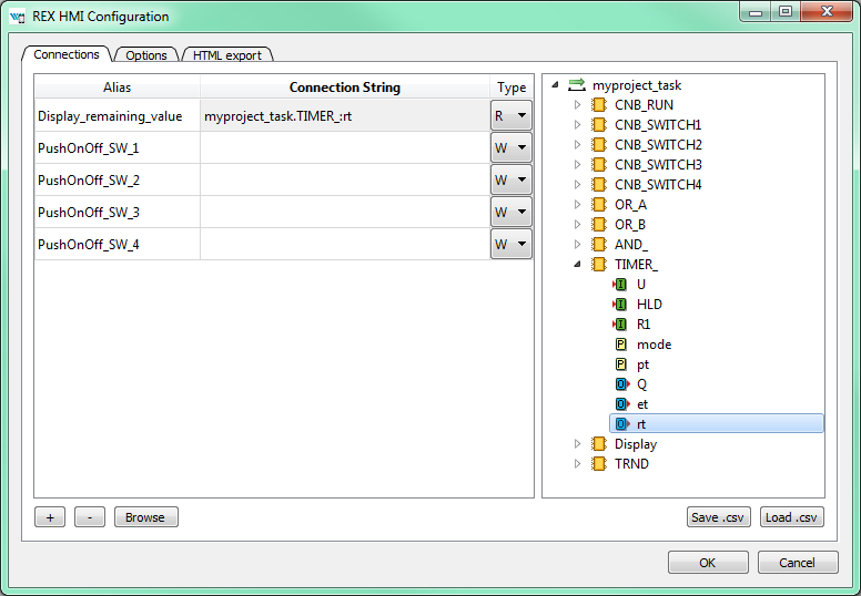
Select Connection String field of the Display_remaining_value item and afterwards browse the tree to the TIMER_ block and double-click the rt parameter. The connection string of the parameter is copied to the Display_remaining_value alias, which is shown in the next figure.
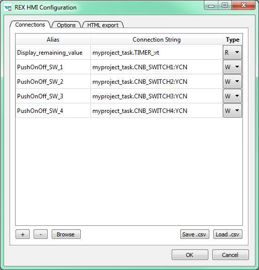
Once the display is linked we will also link the switches. Just browse the tree to CNB_SWITCH1, select the Connection String field of the PushOnOff_SW_1 alias and double-click the YCN parameter. Repeat this for the remaining connection strings. Afterwards press OK to save the settings and close the dialog.
The interactive components in REXYGEN HMI Designer are just parts of the drawing. The user can position the components arbitrarily and add as many decorative static components to as needed. We will add some text descriptions to distinguish individual buttons. Use the Text tool (F8), click anywhere in an empty space and start typing. Pick the Select and Transform tool (F1) afterwards and move the texts and buttons.
Note: More information about custom drawing can be found in Inkscape tutorials (See the Help Tutorials Inkscape: Basic)
A.4 Adding more HMI components
Next we will add more components to control the timer and show the status of the OR and AND blocks. Open the Elements library (Ctrl+L) and add one Input and four Led components. The LEDs will show the status of Boolean values and the Input will be used for changing the default timer interval value.
In the Led components just edit the Title via the Edit Component extension (select the component by single click and press Ctrl+E). The titles should be Led_OR_A, Led_OR_B, Led_AND, and Led_TIMER_OUT respectively. Finally edit the Input component by changing the Title to Input_interval.
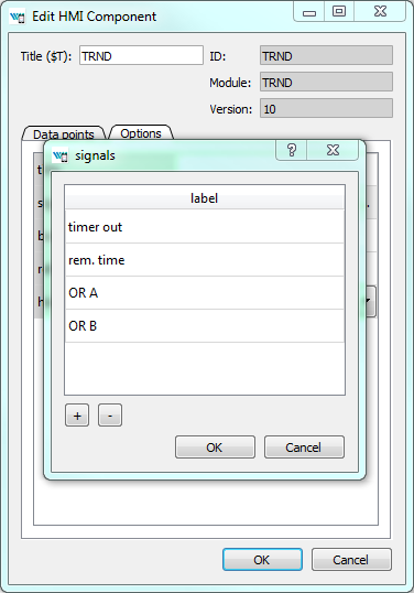
The last component we need is a graph showing the time-plot of data from the TRND block. Use the components library (Ctrl+L) and add a TRND component. You can adjust its size to fit the desired position. Edit the component (Ctrl+E) and change the Title to TRND and switch to the Options tab. Double-click the signals property. Add the following labels using the plus (+) button: timer out, rem. time, OR A, OR B. These labels will be shown in the legend of the graph.
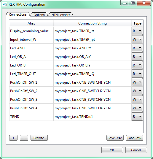
A.5 Additional links to the running algorithm
When all the components are in place we link them to the running algorithm again. Just repeat the procedure described in Section A.3, open the HMI Configuration dialog (Extensions REXYGEN HMI Edit HMI Config and browse the running algorithm to pair the remaining aliases with corresponding connection strings. The list is shown in the following image.
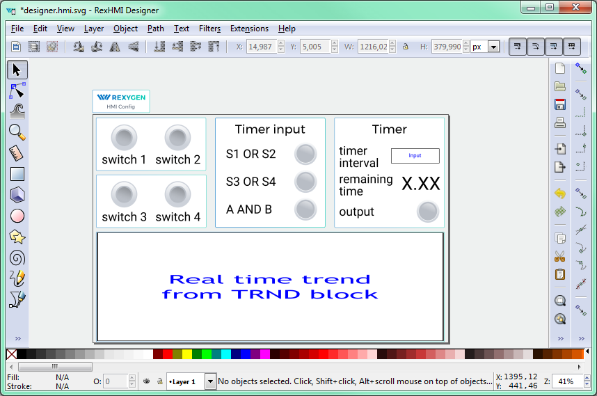
A.6 The final steps
Congratulations, your first graphical HMI is almost ready! Add a few rectangles which will visually divide the HMI into individual sections. Use the Squares and rectangles tool (F4), draw the rectangle, pick a color from the palette and send the rectangle to the background using the End key. Do not forget to save the drawing.
As mentioned earlier, the *.hmi.svg files in the hmisrc folder are automatically processed while the project is compiled in the REXYGEN Studio application. The project main file must contain the HMI block with GenerateRexHMI parameter enabled. This was already covered in Section 4.3 so you should have everything ready.
Once you compile the project again and download it to your Raspberry Pi, the HMI will be
accessible via a web browser. Navigate to
http://192.168.1.100:8008/hmi/designer.html (replace 192.168.1.100 with the IP address
of your UniPi v1.1). You will see your HMI with live data.
This tutorial covers only the very basic components. If you want to get more information about additional components, see [4].
Appendix B
Licensing of the REXYGEN system
The licensing model of the REXYGEN system is quite simple:
- The development tools are free to use, you can install it on as many computers as you want.
- The RexCore runtime module always needs a licence to run on your Raspberry Pi. There are DEMO licences available at no cost and there are permanent licences which you can purchase. Each Raspberry Pi needs an individual licence.
B.1 Obtaining a DEMO licence
The DEMO licence is intended for evaluating, testing and educational purposes. Feel free to experiment with the DEMO licence as long as you need. Commercial use of the DEMO licence is not allowed.
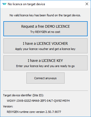
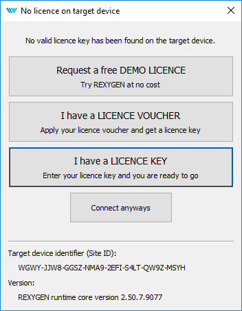
When you try to run your algorithm on a device which does not have a valid licence, you are offered a few options. Unless you already have a licence key or a licence voucher, you’ll need to get a DEMO licence.
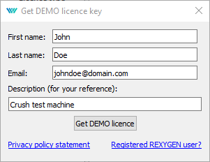
Identify yourself and you’ll receive a DEMO licence key via e-mail. The licence key is called a SiteKey.
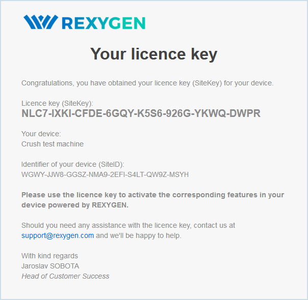
Once you have your DEMO licence key (SiteKey), apply it.

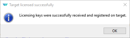
Once successfully applied, your algorithm will download to your UniPi v1.1.
You can review your licence keys in REXYGEN Studio. Go to menu Target Licensing to list the licence keys and activated modules.
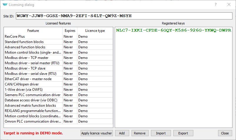
Evaluation version of RexCore (REXYGEN runtime core) is functional for 2 hours. It is possible to run your algorithm on the UniPi v1.1 but you cannot store it permanently. The algorithm resides only in the RAM memory therefore it will not run after a restart or power-up. You can use almost all function blocks, see [1]. The RexCore runtime core on the target device is terminated after 2 hours of operation in demo mode without any warning. After a restart, you have another 2 hours for your experiments.
B.2 Obtaining a permanent licence
It is necessary to activate the RexCore runtime module and optional additional modules for permanent operation. This can be done using the licence, which you can obtain at
B.2.1 Activation of the permanent licence
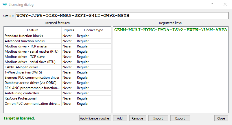
Each device running the RexCore runtime module is identified by the so-called SiteID tag. The purchased licence must be associated with the hardware device, i.e. with the SiteID tag.
- In REXYGEN Studio, connect to the device and go to menu Target
Licensing. A dialog pops up and you will see the SiteID and your licences.
- Delete any DEMO licence keys if present.
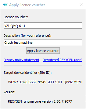
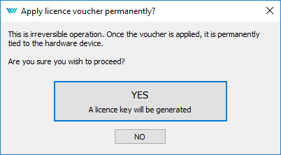
- Afterwards, click the Apply licence voucher button and enter your licence voucher
code.
- You are asked to confirm the association – this is the last and irreversible
step.
- The so-called SiteKey licence key is generated from your licence voucher and it is stored
in your device. The licence key allows permanent operation of the runtime
core.
- To check the licence, make sure the REXYGEN Studio is connected
to the device and open the licensing dialog again (Target
Licensing). Check that the licence was applied correctly and that the RexCore runtime
module no longer runs in demo mode.
- It is highly recommended to check the licence again after a reboot of the device.
Bibliography
[1] REX Controls s.r.o.. Function blocks of REXYGEN – reference manual, 2020. .
[2] REX Controls s.r.o.. RexCore – User manual, 2020. .
[3] REX Controls s.r.o.. REXYGEN Studio – User manual, 2020. .
[4] REX Controls s.r.o.. REXYGEN HMI – User manual, 2020. .
[5] REX Controls s.r.o.. RPiDrv driver of REXYGEN for Raspberry Pi – user guide, 2020. .
Documentation reference number: 14711
2022 © REX Controls s.r.o., www.rexygen.com